


Analog Voice Modules Passport 4400 Hardware Installation Manual
6-5
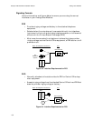
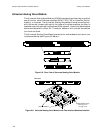
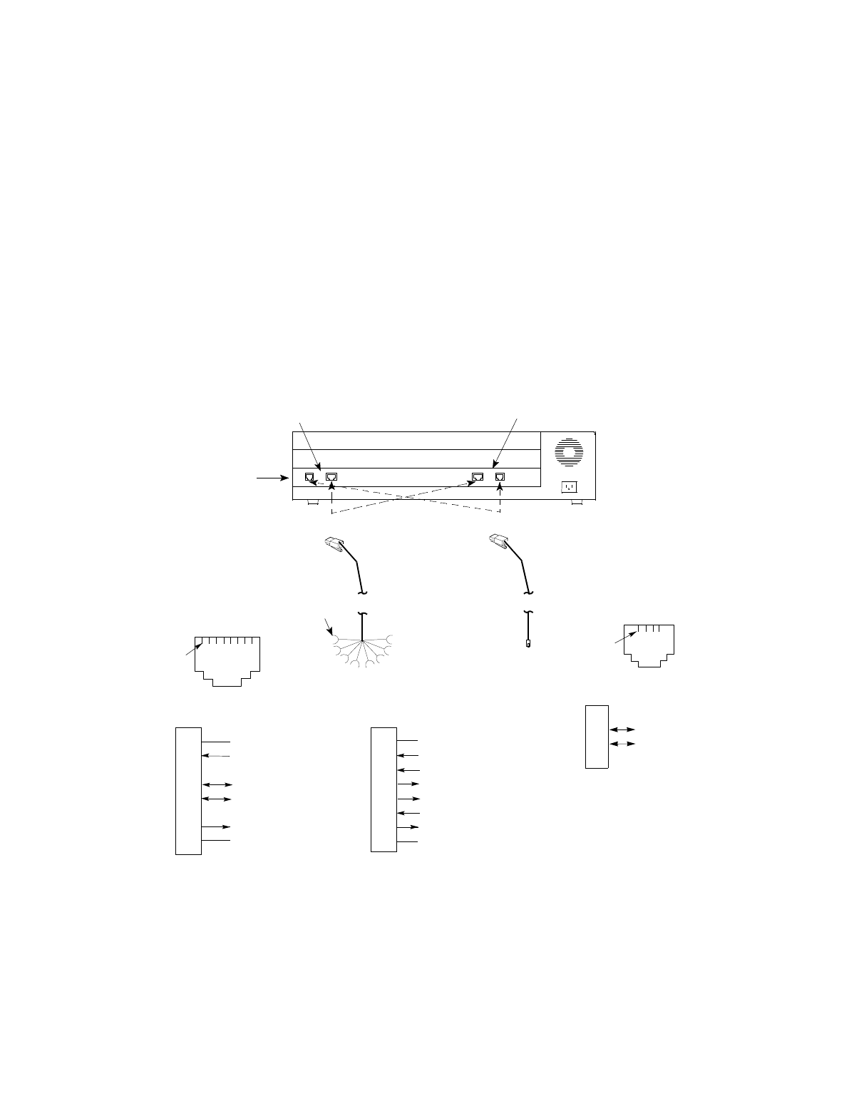
Attaching Cables to the Analog Voice Module
The connections will depend on the specific site requirements. If you are not
sure of the exact connections required for the Passport 4400 unit you are
installing, consult your system administrator.
• If your site requires an E&M connection, use an RJ-48C cable to connect
the Passport 4400 unit to a PBX. The strapping assignments for both 2-
wire and 4-wire cables are shown in Figure 6-20 on page 6-18.
Note:
Refer to Appendix E, PBX Interface Connection Diagrams
for
circuit connection information regarding connecting an E&M
voice channel to a PBX.
• If your site requires an FXS or FXO connection, use an RJ-11 cable to
connect the Passport 4400 unit to a telephone set or wall jack.
Refer to Appendix A, Cable Diagrams, for further information about cables.
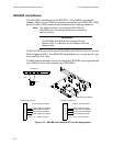
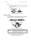
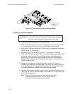
Figure 6-7. Telephone Interface Cable Connections
Analog Voice
Module
Pin 1
RJ-11
Pin 1
Modular cable for E&M
(FXO). Connect to terminal
block associated with the
PBX.
Modular cable for FXS or FXO.
Connect to telephone set or
wall jack.
FXS/FXO
RJ-11 Interface
E&M
RJ-48C Interface
RJ-48C
Voice/Fax
Channel 2
Voice/Fax
Channel 1
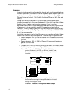
RJ-11 Pin Assignments
and Wire Colors
1
2
3
4
Ring (R), red
Tip (T), green
RJ-48C Pin Assignments
and Wire Colors (4-wire)
1
2
3
4
5
6
7
8
Signal Battery (SB), blue
Mouth (M), orange
Ring 1 (R1), black
Ring (R), red
Tip (T), green
Tip 1 (T1), yellow
Ear (E), brown
Signal Ground (SG), gray
RJ-48C Pin Assignments
and Wire Colors (2-wire)
1
2
3
4
5
6
7
8
Signal Battery (SB), blue
Mouth (M), orange
Ring (R), red
Tip (T), green
Ear (E), brown
Signal Ground (SG), gray
Blue SB
lead
Pins 1, 4 Not Connected
Pins 3, 6 Not Connected