


Index - 2
Analog Voice Modules Part Numbers see
Chapter 1
AT Commands
11-2
B
Back Panel
blanks
10-5
grounding clips
10-5
Base Module see Ethernet Base Module
C
Cable Diagrams see Appendix A
Cabling Requirements
T1 Voice Module
D-1
Calculating
usable cable distance
D-4
Canadian Requirements
iv
equipment attachment limitation
B-13
CE Conformance
2
Configuring
power supplies
9-5
Connecting
AC unit
2-5
,
2-6
Analog Voice Module
6-5
DC unit
2-7
E1 Voice Module
5-4
Ethernet Base Module
3-3
T1 Voice Module
5-2
terminal block
6-9
Connecting the PC
11-1
Connectors
stacking
10-4
Connectors and Pin Assignments
56 kbps CSU/DSU
7-3
Analog Voice Module
6-5
E1 CSU/DSU
7-5
E1 Voice Module
5-5
FXS and FXO Interface Module
6-11
ISDN TA S/T Interface Module
7-7
ISDN TA U Interface Module
7-6
T1 CSU/DSU
7-4
T1 Voice Module
5-3
CSU
1-5
D
Data Modules
1-3
,
4-1
DC Power Connections
2-7
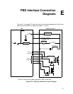
Diagrams
PBX interface connection
E-1
Digital Voice Expansion Module
1-4
,
5-10
indicators
8-6
power harness
5-11
,
9-2
Digital Voice Module
5-12
Digital Voice Modules
1-4
16 Mbyte Flash Memory
3-7
DVEM power harness
5-11
E
E&M
interface module
6-17
strapping
6-17
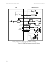
PBX interface connections
E-1
specifications
C-6
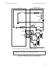
E&M Type II
PBX interface connections
E-2
E&M Type V
PBX interface connections
E-3
E1 CSU/DSU Interface Module
1-5
,
7-4
pin assignments
7-5
E1 Voice Module
1-4
,
5-4
agency compliance
B-4
connecting
5-4
dual port
5-4
pin assignments
5-5
specifications
C-3
indicators
8-2
operational states
8-5
single port
5-4
pin assignments
5-5
strapping
5-5
Ear and Mouth (E&M)
1-4
Environmental Specifications
2-3
Ethernet Base Module
1-3
,
3-1
components
3-1
connecting
3-3
ethernet access port
3-6
pin assignments
3-6
Frame Relay DCE
3-4
pin assignments
3-5
indicators
8-1
management port
3-4
pin assignments
3-4