


PBX Interface Connection Diagrams Passport 4400 Hardware Installation Manual
E-3
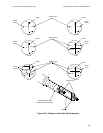
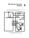
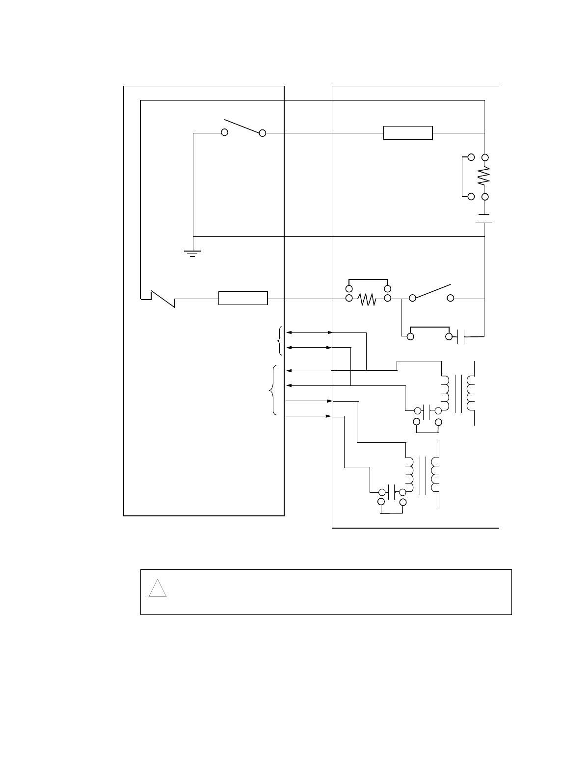
* Install jumpers when cable distance to PBX is too long.
Figure E-26. E&M Type V Interface Connection Diagram
Caution:
!
** PBX SB and Voice Module SB are to be connected only when
-48 volt supply is not available on the PBX side.
DETECTOR
-48 V
M
EE
M
DETECTOR
SB
**
SB
UAVM only: E15
T
T1
R
R1
+
+
T
R
2-Wire
Operation
4-Wire
Operation
GND SG
+
-
UAVM only:
E16
AVM: -44 V
UAVM: -42 V
AVM: E41, channel 1
E38, channel 2
UAVM: E14
*
*
UAVM only: E17
UAVM only: E8
E&M Interface Type V
PBX