


Ethernet Base Module Passport 4400 Hardware Installation Manual
3-3
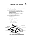
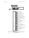
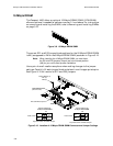
Port 2 and Port 3 are slots for optional plug-in Interface Modules supporting
the following options:
• 56 Kb/s CSU/DSU
• T1 CSU/DSU
• E1 CSU/DSU
• ISDN U and S/T Interfaces
• Serial WAN
For more information on the interface modules, refer to Chapter 7, Interface
Modules (WAN).
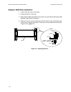
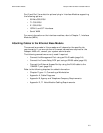
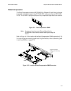
Attaching Cables to the Ethernet Base Module
The connections made in this procedure will depend on the specific site
requirements. If you are not sure of the exact connections required for the
Passport 4400 unit, consult your system administrator.
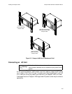
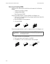
The following connections are only used if required.
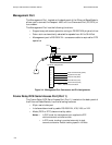
• Connect the Management Port using an RJ-45 cable (page 3-4)
• Connect the Frame Relay DCE port using a DB-50 cable (page 3-5)
• Connect the Ethernet Access Port by using the RJ-45 cable to the
10BASE-T port (page 3-6)
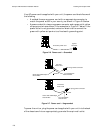
Refer to the following chapters for added information:
• Chapter Figure 11, Connecting a Workstation
• Appendix A, Cable Diagrams
• Appendix B, Agency and Telephone Company Requirements.
• Appendix D, T1 Voice Module Cabling Requirements.