


T1, E1, and Digital Voice ModulesPassport 4400 Hardware Installation Manual
5-6
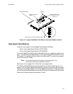
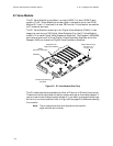
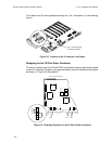
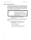
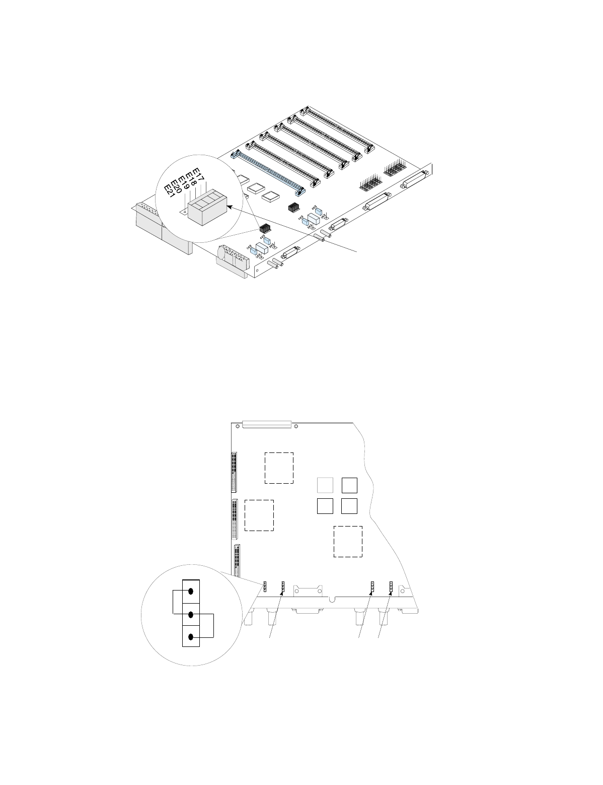
The locations of the two impedance straps for line 1 are shown in the following
figure.
Figure 5-5. Location of the E1 Interface Line Straps
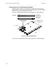
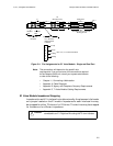
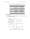
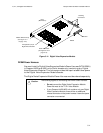
Strapping for the 75 Ohm Outer Conductor
The outer conductors of the 75 ohm BNC interface connectors may be connected
to earth or isolated. Strapping is implemented by a set of headers and jumpers
as shown in Figure 5-6 on page 5-6.
Figure 5-6. Strapping Positions
for the 75 Ohm Cluster Conductor
Line 1 75 ohms select.
120 ohms as shown.
1
2
3
EARTH
OPEN
E83
E78 E71
E66
Fron
t o
f E
1 A
cces
s M
odule