


Analog Voice ModulesPassport 4400 Hardware Installation Manual
6-20
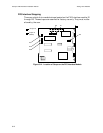
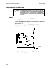
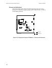
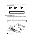
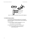
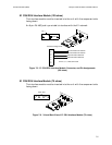
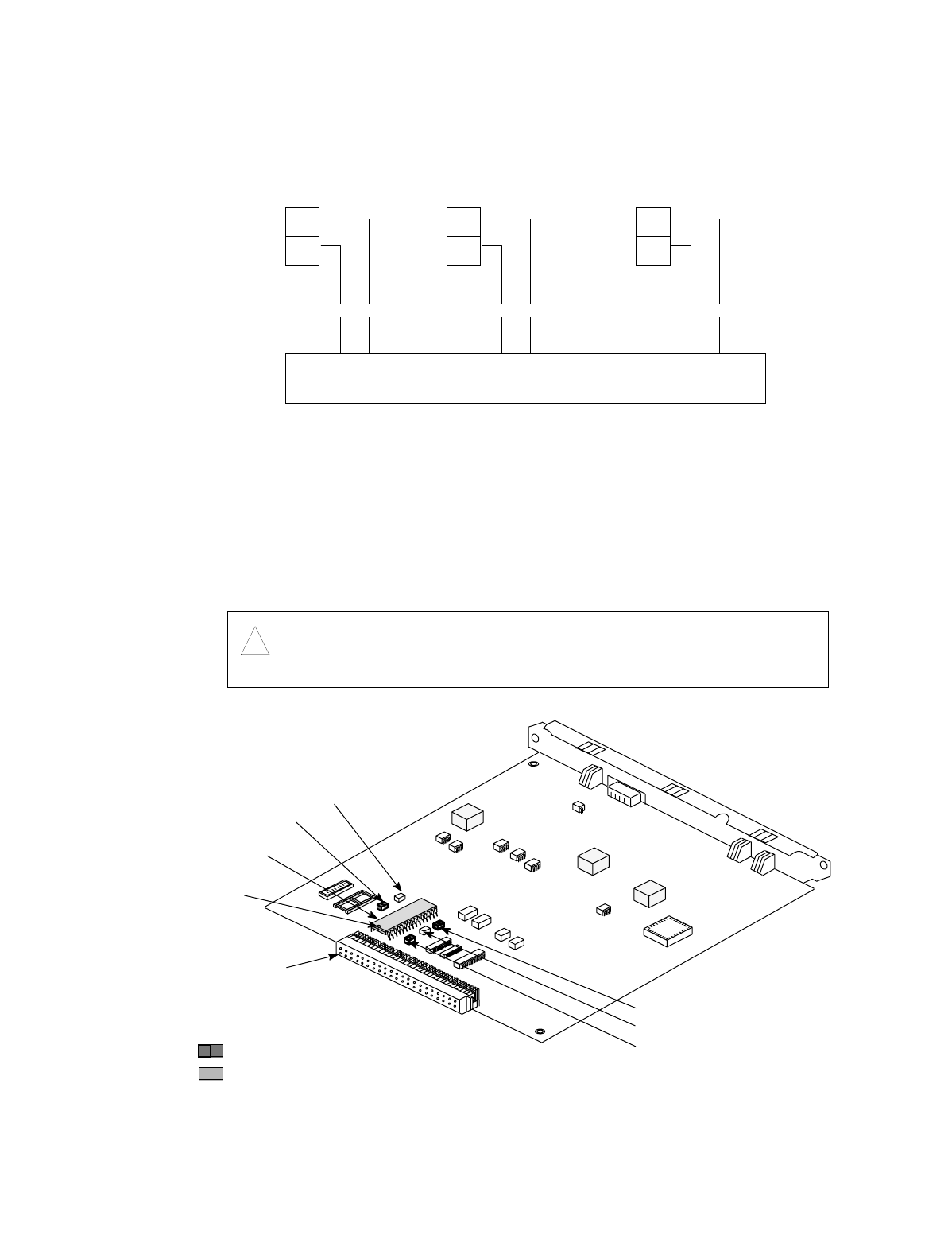
Figure 6-22 is a wiring diagram of the interface connectors. Note that the 8-pin
terminal block is connected in parallel with the three modular RJ-11 connectors
(pins 3 and 4 are not used).
Figure 6-22. Interface Connection Wiring Diagram
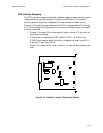
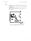
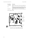
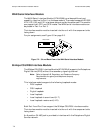
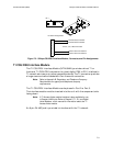
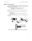
Strapping and PROM Orientation
There are a total of five movable straps located on the Voice/Fax Switch Module,
E1 through E5. These straps are preset at the factory to match the type of
memory installed. These straps must not be altered by the user.
Figure 6-23. Location of Straps and PROM on Voice/Fax Switch Module
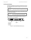
Caution:
!
PROM U2 must be oriented as shown in Figure 6-23, with the
notch facing connector P1. Otherwise, it may result in damage to
the PROM.
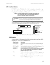
FXS
2
3
8 7
FAX
2
3
RF TF
6 5
PSTN
2
3
R T
2 1
RP TP
= Jumper in (default position)
= Jumper out
PROM U2
Connector P1
E1
Notch
E2
E3
E4
E5