


T1 Voice Module Cabling RequirementsPassport 4400 Hardware Installation Manual
D-2
Shielded Cable Construction
Typical telephone cable consists of plastic-coated pairs of 22- or 24-gauge wire
(very seldom l9-gauge) with a mutual capacitance of 0.083 uF/mile. The cable
should be in good repair, free of moisture, and have satisfactory transmission
characteristics at 772 kHz (loss of less than -33-# dB and crosstalk of less than
-63 dB).
Each wire pair is uniquely color coded to distinguish it from all other wire pairs.
A total of 25 different color codes are used for wire pairs. On larger cables with
more than 25 wire pairs, the wires are formed into 25-pair groups, with each
group repeating the same color-coding scheme. To distinguish one group from
the next, each 25-pair group is itself color coded.
In cables of 100 pairs or larger, these color-coded groups are maintained and
termed binder groups. In smaller cables, it is occasionally necessary to subdivide
the color-coded group into separately wrapped pairs to form a smooth cable
assembly. These subdivided groups preserve the color-coding, but, electrically,
they are now in separate binder groups.
New cables now segregate the pairs within a cable into shielded compartments
or groups, completely separating the transmit and receive pairs. This
improvement to the near-end coupling losses of paired cables is achieved by the
use of a special heavy-gauge foil barrier (screen) shielding. This effectively
creates two cables within a single jacket. Crosstalk between sections is typically
less than -100 dB. Examples of this type of cable are the T-Screen and D-Screen
products offered by Superior Cable and General Cable, respectively.
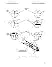
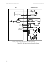
Figure D-23. illustrates the cross sections of this type of shielded cables. As an
example, consider the cable consisting of 12 wire pairs, divided by the shield
into two binder groups. For span line 1, match wire pair 1 in one binder group
with wire pair 7 in the other binder group; for span line 2, wire pair 2 would be
matched with wire pair 8, and so on. Where the number of wire pairs is odd,
such as the 25-pair cable, pairs 1 through 12 would be assigned one transmission
direction, with pairs 13 through 24 assigned the corresponding return paths.
Pair number 25 was not used. In the case of an even-pair cable, such as the 50-
pair cable, pairs 1 through 25 are available for one transmission direction, while
the corresponding pairs 26 through 50 are used for the corresponding return
paths, with no pair left over.