


T1, E1, and Digital Voice Modules Passport 4400 Hardware Installation Manual
5-7
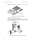
Table 5-1. Outer Conductor Jumper Settings for the 75 Ohm Connector
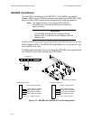
Pin Assignments
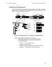
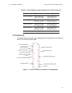
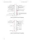
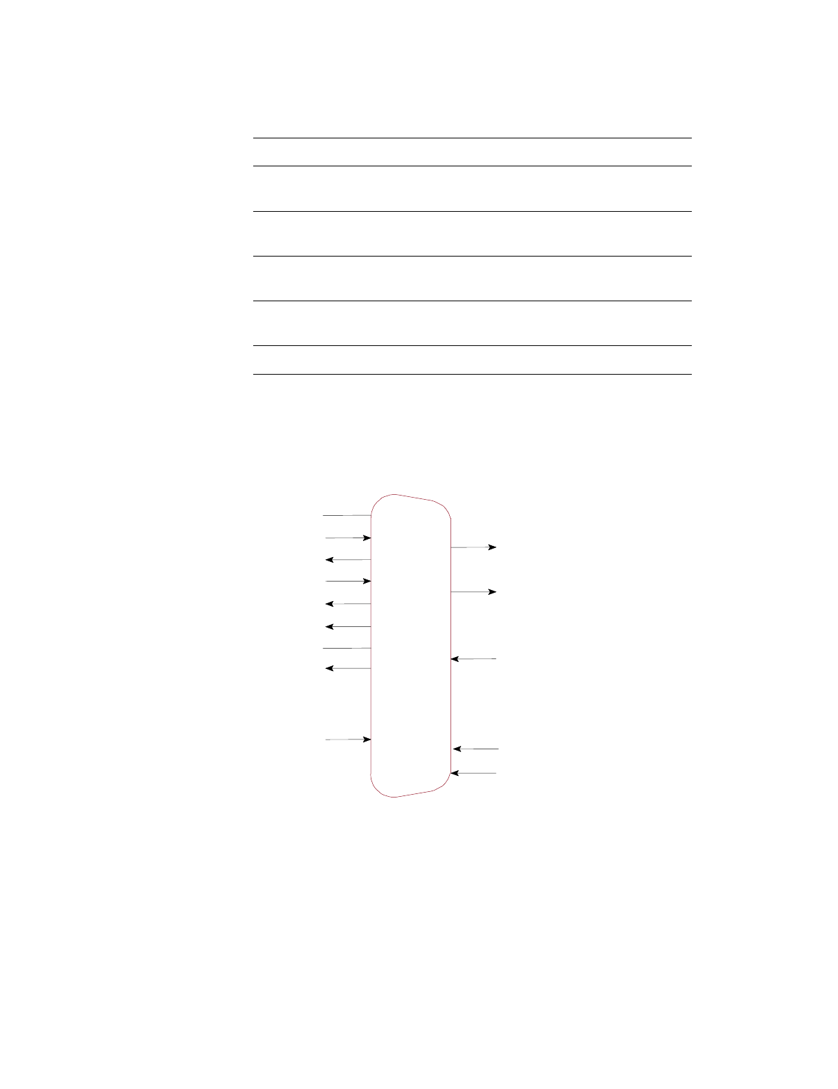
The following figures show the pin assignments of the data port connectors for
each of the three interface types.
Figure 5-7. RS-232/V.24 Data Port Connector Pin Assignments
Connector To Earth Isolated (Open)
Line 1 Rx (DSX-1) Place jumper over
E83, pins 1 and 2.
Place jumper over
E83, pins 2 and 3.*
Line 1 Tx (DSX-1) Place jumper over
E78, pins 1 and 2.*
Place jumper over
E78, pins 2 and 3.
Line 2 Rx (DS-1) Place jumper over
E71, pins 1 and 2.
Place jumper over
E71, pins 2 and 3.*
Line 2 Tx (DS-1) Place jumper over
E66, pins 1 and 2.*
Place jumper over
E66, pins 2 and 3.
* Indicates factory default setting
1
2
3
4
5
6
7
8
9
10
11
12
13
14
15
16
17
18
19
20
21
22
23
24
25
Frame Ground (FGND)
T
ransmit Data (TD)
Receive Data (RD)
Request-to-Send (R
TS)
Clear-to-Send (CTS)
Data Set Ready (DSR)
Ground
Data Carrier Detect (DCD)
Unassigned (UNA)
(TC) T
ransmit Clock
(RC) Receive Clock
(DTR) Data T
erminal Ready
(BI) Busy
(ETC) External T
ransmit Clock