


T1, E1, and Digital Voice Modules Passport 4400 Hardware Installation Manual
5-5
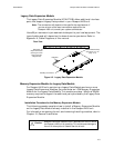
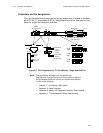
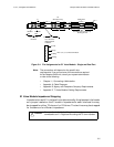
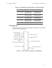
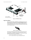
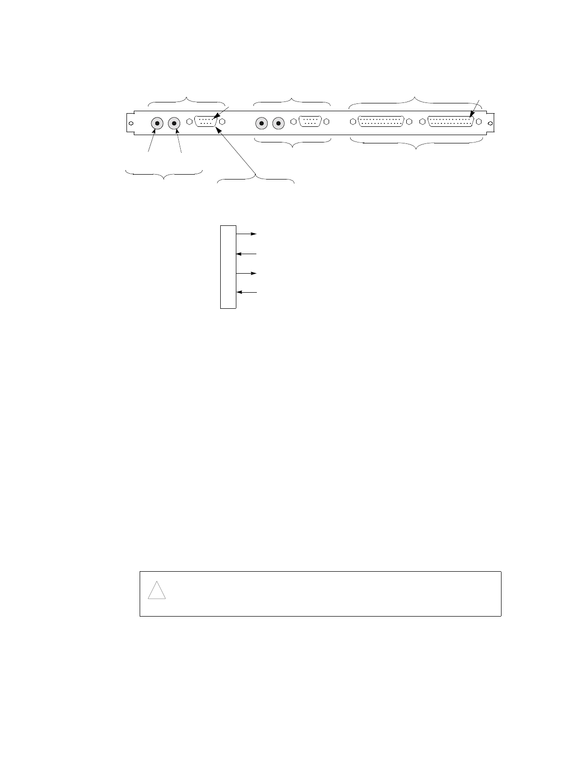
Figure 5-4.
Pin Assignments
for E1 Voice Module - Single and Dual Port
Note:
The connections will depend on the specific site
requirements. If you are not sure of the connections required
for the Passport 4400 unit, consult your system administrator
or refer to the following:
• Chapter 11, Connecting a Workstation.
• Appendix A, Cable Diagrams.
• Appendix B, Agency and Telephone Company Requirements.
• Appendix D, T1 Voice Module Cabling Requirements.
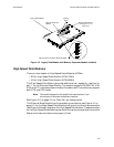
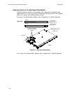
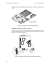
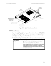
E1 Voice Module Impedance Strapping
Impedance for each E1 interface line is determined by the placement of a header
on a jumper located on the E1 module. Impedance for each interface line may
be strapped for either 75 ohms or for 120 ohms. The two lines may be strapped
for the same or for different impedance.
Caution:
!
For operation in the United Kingdom, this equipment may not be
connected to an E1 Digital service using the 75 ohm interface.
L1
For 75 ohms
Interface
Receive
Pair
Transmit
Pair
DB-9 Connector
For 120 ohms
Balanced pair
Interface
1
2
3
4
5
6
7
8
Tx Tip
Rx Tip
Tx Ring
Rx Ring
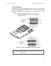
Data Ports
Pins 2, 4, 5, 7, 9 Not Connected
L2
(dual-port only)
Same as Line 1
See Figure 5-7, Figure 5-8,
and Figure 5-9
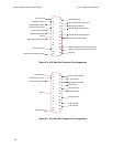
Pin 1
Pin 1