


Index-4
75 ohm connector
5-7
L
LED, see Indicators
8-1
Legacy Data Expansion Module
4-3
agency compliance
B-10
connecting
4-3
Legacy Data Module
4-2
agency compliance
B-10
Memory Expansion Module
4-3
pin assignments
4-2
LIM (Logical Interface Module)
identifier
10-2
settings
10-2
Logical Interface Module
switches
10-4
M
Management Cable
11-2
Memory Expansion Module
installation
4-3
Legacy Data Module
4-3
Modem Configuration
11-2
Modem Connection
11-2
Module Stacking Order
10-1
N
Notice of Electromagnetic Compatibility
(EMC)
B-1
Null-modem
11-2
O
Operating Environment
C-1
power requirements
C-1
relative humidity
C-1
temperature
C-1
P
Passport 4400
3-slot
space requirements
2-2
5-slot redundant power supply
space requirements
2-2
models
1-1
operating environment
C-1
physical dimensions
C-1
rack installation
2-4
rackmount kit
2-3
unpacking
2-3
Passport 4430/4450/4455
1-1
Passport Management Cable
11-2
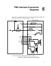
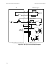
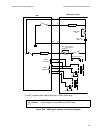
PBX Interface Connections
diagrams
E-1
E&M
E-1
E&M Type II
E-2
E&M Type V
E-3
PC Connection
11-1
Pin Assignments
56 kbps CSU/DSU Serial Interface
7-3
data port connectors
5-7
RS-232
5-7
V.35
5-8
X.21
5-8
E1 Voice Module
dual port
5-5
single port
5-5
FXS and FXO Interface Modules
6-11
ISDN TA S/T Interface Module
7-7
ISDN TA U Interface Module
7-6
T1 CSU/DSU Serial Interface
7-4
,
7-5
Pin Assignments for Cables see Appendix A
Power
configuring the power supplies
9-5
DC
power supply
9-4
power harness for DVEM
9-2
redundant power supply
9-3
Power harness for DVEM
5-11
Power Supplies
3-slot chassis
9-1
5-slot chassis
9-2
5-slot chassis with redundant power
supply
9-3
Preparing the Site
installation
2-1
R
Removing
connector cover (UAVM)
6-7
daughterboards
5-13
interface module (UAVM)
6-8