


Analog Voice Modules Passport 4400 Hardware Installation Manual
6-17
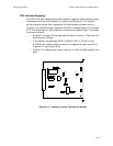
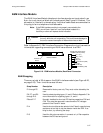
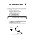
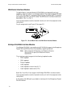
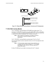
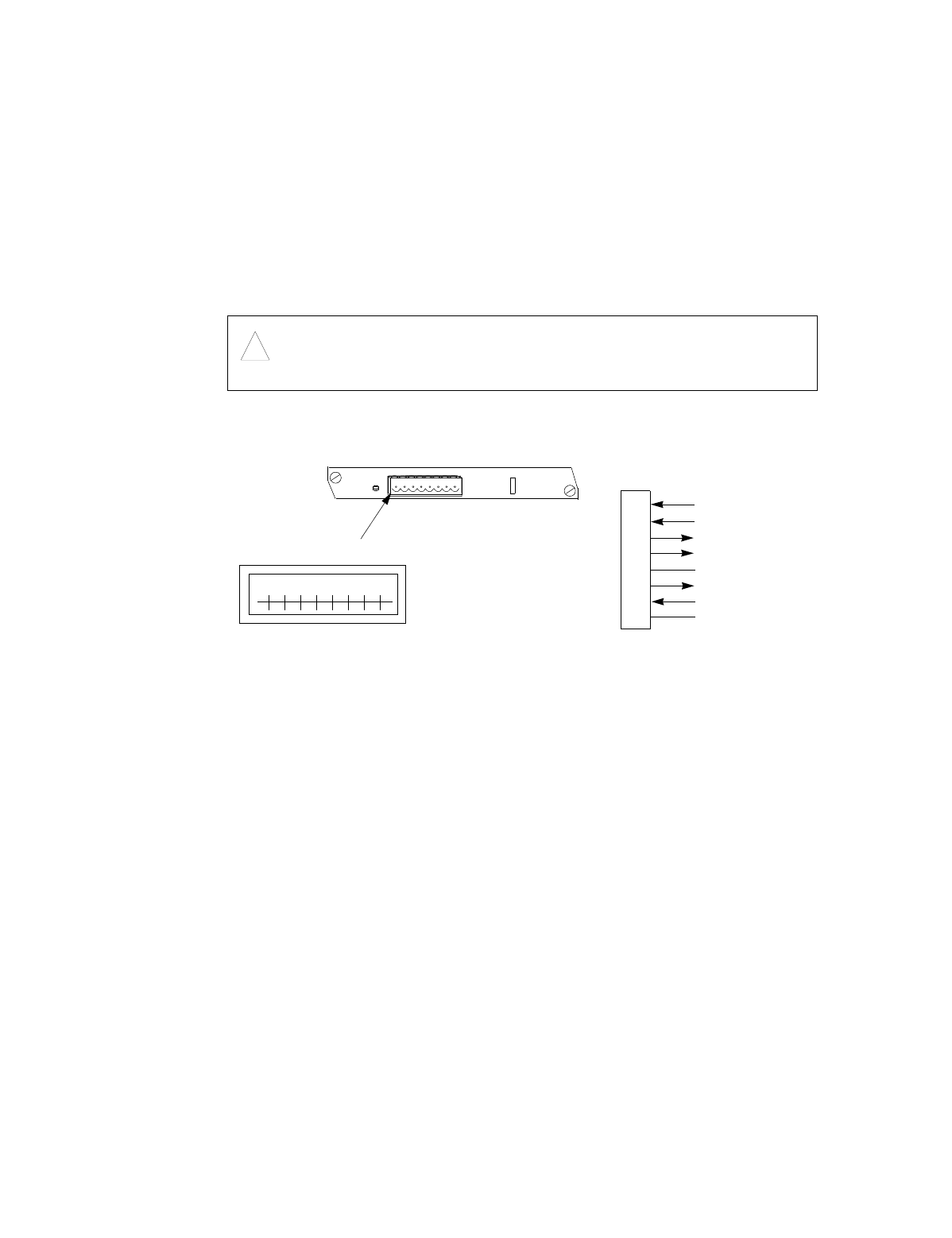
E&M Interface Module
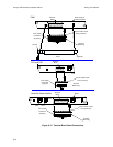
The E&M Interface Module telephone interface signals are terminated in an
8-pin tie trunk terminal block on the back panel (see Figure 6-19 below). This
connector is fitted with a female plug. Individual cable leads are connected to
this plug to form a telephone interface cable.
Note:
If the E&M interface module is not properly connected to the
PBX, you will hear “dead air” over the handset instead of a
fast busy or other call request denial indication.
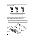
Refer to Appendix E, PBX Interface Connection Diagrams for circuit connection
information regarding connecting an E&M voice channel to a PBX.
Figure 6-19. E&M Interface Module, Back Panel Connector
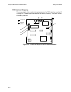
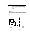
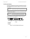
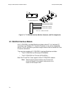
E&M Strapping
There are a total of 22 straps on the E&M interface module (see Figure 6-20,
on page 6-18). Their functions are as follows:
Caution:
!
The interface module must not be inserted into, or removed from
the unit, while the unit is operating. This could cause damage to
the unit or cause interruption of network services or both.
Strap Number Description
E1 through E5 Reserved for factory use only. They must not be altered by the
user.
E6, E7, and E9
through E13.
Used to select signaling types I, II, and V. Refer to Appendix C for
more information on signaling types I, II, and V.
E8 and E17 Normally installed to shunt out DC blocking capacitors C36 and
C38. They must be removed in case there are DC voltages
present in the R and R1 leads.
E14 Used to shunt out the series resistor in the E lead in case the loop
resistance is too high to trip the detector inside the PBX. If ca-
bling is short, try removing the strap.
E15 Used for dial pulse correction; it connects a 1-
µ
f filter capacitor
between the SG lead and ground.
E&M
Interface Module
1
Te r mi n al
Block
RJ-48C Pin Assignments
and Wire Colors (4-wire)
1
2
3
4
5
6
7
8
Tip 1 (T1)
Ring 1 (R1)
Tip (T)
Ring (R)
Signal Ground (SG)
Ear (E)
Mouth (M)
Signal Battery (SB)