


Analog Voice Modules Passport 4400 Hardware Installation Manual
6-11
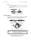
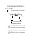
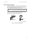
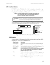
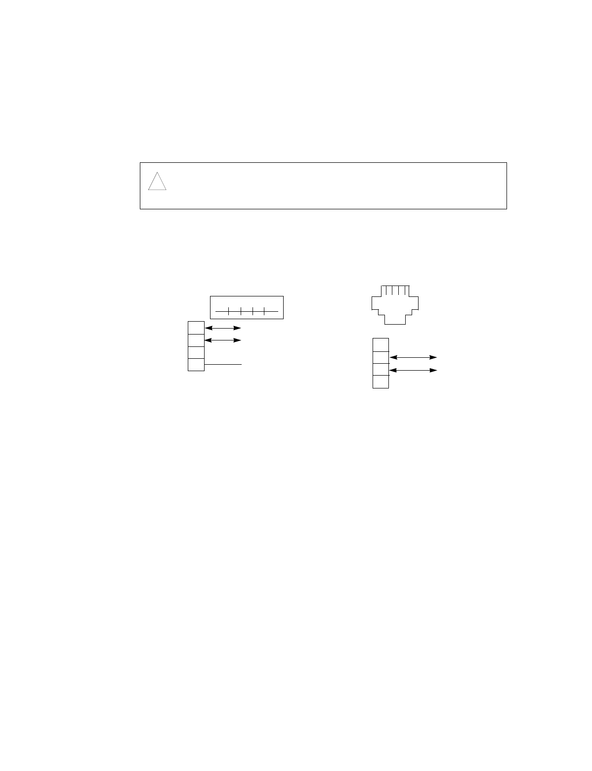
FXS and FXO Interface Modules
Except for the type designation, the FXS and FXO interface modules have
identical telephone interface connectors on the back panel. Each consists of an
RJ-11 modular jack labeled FXS or FXO and a 4-pin terminal block; see
Figure 6-13 below. Both are shielded by a protective cover.
The terminal block is fitted with a female plug. Individual cable leads are
connected to this plug to form a telephone interface cable.
Refer to Figure 6-10 on page 6-7 for more information.
Figure 6-13. FXS and FXO Interface Modules
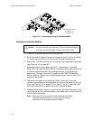
Caution:
!
The interface module must not be inserted into, or removed from
the unit, while the unit is operating. This could cause damage to
the unit or cause interruption of network services or both.
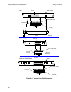
1
2
3
4
1
2
3
4
Tip (T)
Ring (R)
Signal Ground (SG)
Te r m i n a l
Block
FXS or FXO
RJ-11
RJ-11
1
Tip (T)
Ring (R)
1
Pin 3 not connected
Pins 1, 4 not connected
Terminal Block
Note:
Pin 1 must not be connected.