


Power SuppliesPassport 4400 Hardware Installation Manual
9-6
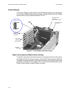
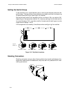
Notes: •
Jumper position one is strapped only when you have a
redundant power supply installed. Notice for a 5-slot
standard model that position number one is not strapped,
regardless if it has 1 to 3, or 4 to 5 modules installed
•
Jumper position six is strapped for all 5-slot models
regardless of the number of modules installed
•
Jumper position eight is for detecting failed power
supplies. Make sure that position eight is NOT strapped
for a 5-slot model with 4 to 5 modules installed. If position
eight is strapped, then the unit can not detect if the fourth
or fifth power supply fails. This strap is installed at the
factory and needs to be removed when you add the
fourth module
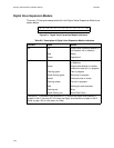
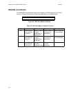
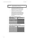
Table 9-2. Jumper 12 Strapping for the AC Units
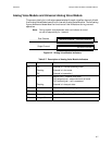
Table 9-3. Jumper 12 Strapping for the DC Units
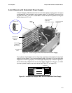
Caution:
!
Prior to turning on your unit, be sure to check the straps for proper
positioning according to the particular unit you have. Incorrect
strapping will cause the unit to malfunction.
Passport 4400 Unit
Model and Configuration
Jumper Positions (J-12)
1 2 3 4 5 6 7 8
5-slot standard, AC, 1 to 3 modules
X X X X X X X
5-slot standard, AC, 4 to 5 modules
X X X X X X
5-slot redundant, AC, 1 to 3 modules
X X X X X X X X
5-slot redundant, AC, 4 to 5 modules
X X X X X X
Passport 4400 Unit
Model and Configuration
Jumper Positions (J-12)
1 2 3 4 5 6 7 8
5-slot standard, DC, 1 to 3 modules
X X X X X X
5-slot standard, DC, 4 to 5 modules
X X X X X
5-slot redundant, DC, 1 to 3 modules
X X X X X X X
5-slot redundant, DC, 4 to 5 modules
X X X X X