


E-1
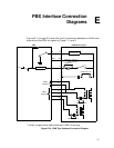
PBX Interface Connection
Diagrams
E
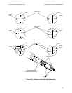
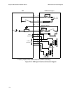
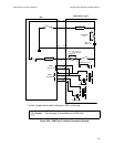
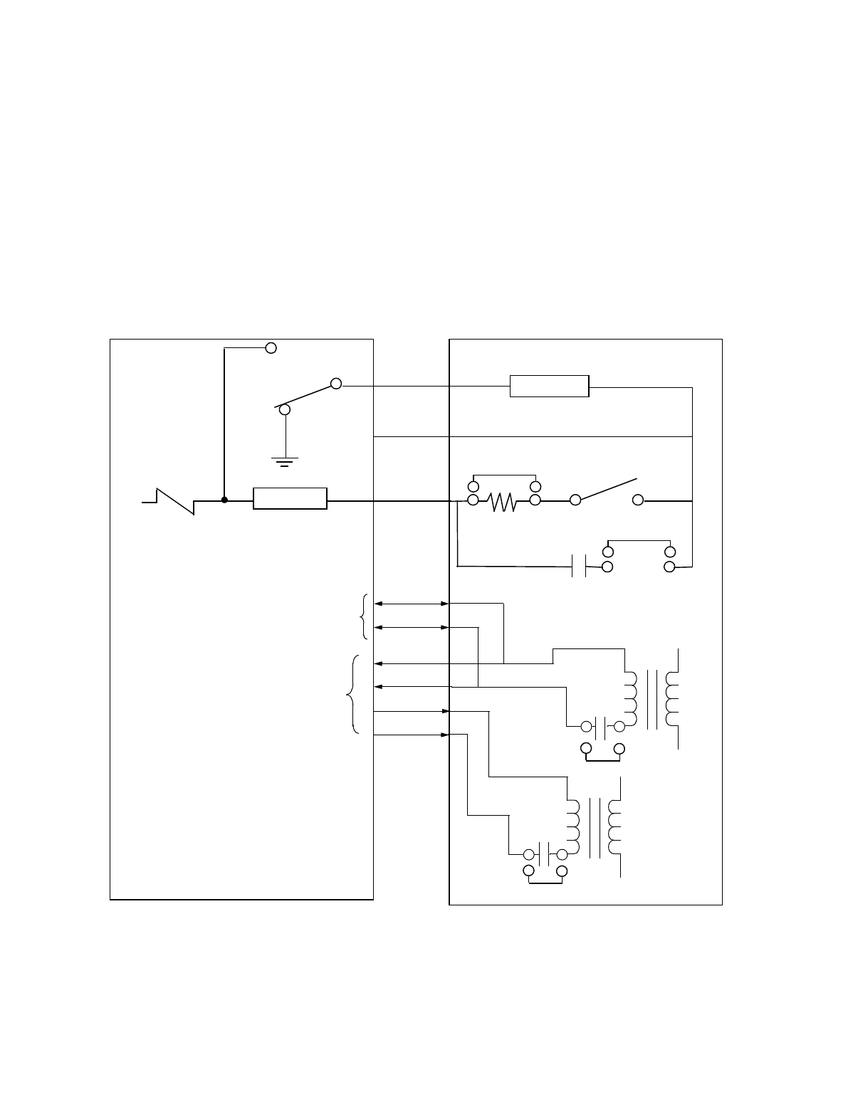
Figures E-1 through E-3 show the circuit connections between an E&M voice
channel and the PBX for signaling Types I, II, and V.
* Install jumpers when cable distance to PBX is too long.
Figure E-24. E&M Type Interface Connection Diagram
-48 V
M
GND
EE
M
SG
DETECTOR
DETECTOR
T
T1
R
R1
+
+
T
R
2-Wire
Operation
4-Wire
Operation
AVM: E41, channel 1
E38, channel 2
UAVM: E14
*
UAVM only: E15
UAVM only: E17
UAVM only: E8
E&M Interface Type I
PBX