


CHAPTER 3: Replacing notebook components
94
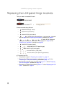
Replacing the LCD assembly lid
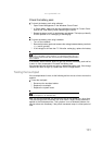
Tools you need to complete this task:
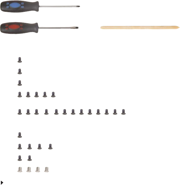
Screws removed during this task:
• 3 black M2.5×6 (bay cover)
• 1 black M2×3 (hard drive)
• 1 black M2.5×6 (optical drive)
• 5 black M2×3 (keyboard frame - top base side) - Indicated
by A in step 8 of the “Replacing the keyboard” procedure on page 53
• 13 black M2.5×6 (keyboard
frame/palm rest module - base side) - indicated by B in step 8 of the
“Replacing the keyboard” procedure on page 53
• 1 black M2×3 (system board)
• 4 black M2.5×6 (LCD panel hinges)
• 2 black M2.5×5 (LCD front panel)
• 4 chrome M2.5×4 (LCD panel)
To replace the LCD assembly lid:
1 Complete the steps in “Preparing the notebook” on page 37.
2 Remove the LCD panel assembly by performing steps 2 – 12 of the
“Replacing the LCD panel assembly” procedure on page 76.
3 Remove the LCD front panel by performing steps 3 – 5 of the “Replacing
the LCD front panel” procedure on page 79.
4 Remove the LCD panel by performing steps 4 – 7 of the “Replacing the LCD
panel” procedure on page 84.
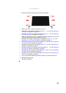
5 If you are going to use the same webcam, microphone and wireless
antennas, remove these items from the old LCD assembly lid and attach
them to the new one. Refer to the related replacement procedure on previous
pages for instructions.
6 Reinstall the LCD panel by performing steps 11 – 14 of the “Replacing the
LCD panel” procedure on page 84.
7 Reinstall the LCD front panel by performing steps 6 – 9 of the “Replacing
the LCD front panel” procedure on page 79.
Make sure the webcam lens is aligned with camera peephole on the LCD
front panel before you secure the panel in place.
8 Reinstall the LCD panel assembly by following the steps 13 – 15 of the
“Replacing the LCD panel assembly” procedure on page 76.
Phillips #0 screwdriver
Flat screwdriver or Non-marring plastic scribe