MIB Descriptions
C-16
7610-A2-GB20-10November 1997
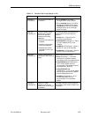
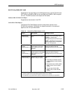
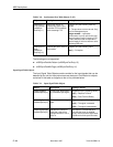
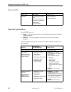
Table C-10. Synchronous Port Table Objects (2 of 2)
Object Setting/ContentsDescription
rs232SyncPort
RTSCTSDelay
(rs232Sync
PortEntry 11)
Reports the interval (in
milliseconds) that the port
waits after RTS is asserted
before asserting CTS.
Supports only the following read-only
values:
0 – The port does not have to wait. Only
valid for Management port.
integer number – represents
milliseconds. It is only valid for the user
data port, when Carrier Control by RTS
is set to Switched and corresponds to
approximately 21 bit time intervals at the
operating DDS rate.
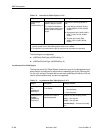
rs232SyncPort
Mode
(rs232Sync
PortEntry 12)
Specifies the port’s mode of
data transfer.
Supports only the following value:
fdx(1) – Full-duplex
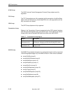
The following are not supported:
H rs232SyncPortIdle Pattern
(rs232SyncPortEntry 13)
H rs232SyncPortMinFlags
(rs232SyncPortEntry 14)
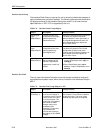
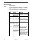
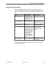
Input Signal Table Objects
The Input Signal Table Objects contains entries for the input signals that can be
detected by the unit for the synchronous user data port. Clarification for objects
contained in this table as it applies to the unit is provided below.
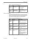
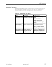
Table C-11. Input Signal Table Objects
Object
Description Setting/Contents
rs232InSigName
(rs232InSigEntry 2)
Contains the identification
of a hardware input signal.
Supports only the following values:
rts(1) – Request To Send
dtr(4) – Data Terminal Ready
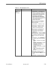
rs232InSigState
(rs232InSigEntry 3)
Contains the current signal
state.
Supports only the following values:
on(2) – The signal is asserted
off(3) – The signal is deasserted
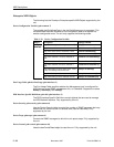
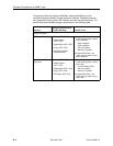
rs232InSigChanges
(rs232InSigEntry 4)
Indicates the number of
times that a signal has
changed from on to off, or
off to on.
The object is incremented each
time that the signal is sampled
(every 100 ms) and the signal state
is different from the previous state.


