


WR1500 4-Port Wireless DSL/Cable Router
®
178
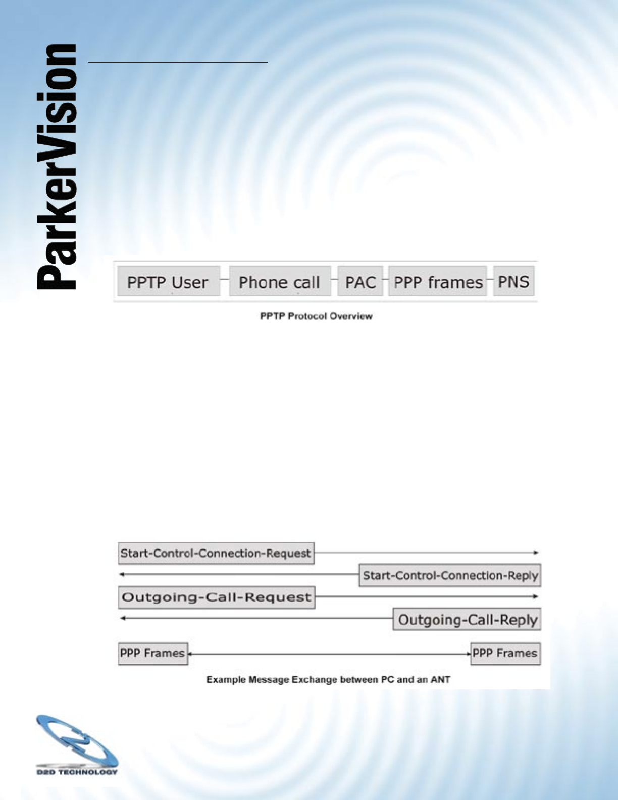
PPTP Protocol Overview
PPTP is very similar to L2TP, since L2TP is based on both PPTP and L2F (Cisco’s Layer 2
Forwarding). Conceptually, there are three parties in PPTP, namely the PNS (PPTP Network
Server), the PAC (PPTP Access Concentrator) and the PPTP user. The PNS is the box that
hosts both the PPP and the PPTP stacks and forms one end of the PPTP tunnel.
The PAC is the box that dials/answers the phone calls and relays the PPP frames to the PNS.
The PPTP user is not necessarily a PPP client (can be a PPP server too). Both the PNS and
the PAC must have IP connectivity; however, the PAC must in addition have dial-up capability.
The phone call is between the user and the PAC and the PAC tunnels the PPP frames to the
PNS. The PPTP user is unaware of the tunnel between the PAC and the PNS.
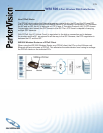
Microsoft includes PPTP as a part of the Windows OS. In Microsoft’s implementation, the PC,
and hence the WR1500 Wireless Router, is the PNS that requests the PAC (the ANT) to place
an outgoing call over AAL5 to an RFC 2364 server.
Control & PPP connections
Each PPTP session has distinct control connection and PPP data connection.
Call Connection
The control connection runs over TCP. Similar to L2TP, a tunnel control connection is fi rst
established before call control messages can be exchanged. Please note that a tunnel control
connection supports multiple call sessions.
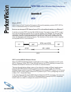
The following diagram depicts the message exchange of a successful call setup between a
PC and an ANT.
The PPP frames are tunneled between the PNS and PAC over GRE (General Routing
Encapsulation, RFC 1701,1702). The individual calls within a tunnel are distinguished using
the Call ID fi eld in the GRE header.