


20 Pelco Manual C1000M-B (1/96)
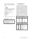
4.10.4 Memory Tests
By entering 4 in this menu the following sub-menu is
displayed:
MEMORY TEST MENU
1. RAM TEST
2. VIDEO RAM TEST
3. (DL) NV MEMORY TEST
4. ROM CRC TEST
By selecting 1, the unit will perform a self test on its
Random Access Memory. This test is used to verify
system RAM integrity. The system will display an OK
message if the test passes or an address and data if it
fails. ESC brings the Inter-Check ICI1000S Series back
to the DIAGNOSTICS MENU.
Selecting 2 in this menu will put the Inter-Check
ICI1000S Series into the VIDEO RAM TEST mode.
The video RAM is verified by a slotted, scrolling dis-
play in the upper left hand corner of the monitor. If an
error is detected an address and data will appear on the
screen. ESC brings the unit back to the DIAGNOS-
TICS MENU.
WARNING: When the NON-VOLATILE
MEMORY TEST is selected all programming
is lost.
The NV MEMORY TEST, (3rd selection), is used to
verify the NON-VOLATILE MEMORY integrity. The
system will display OK if the test passes. Upon error,
the Inter-Check ICI1000S Series will display an address
and the data that was written into the memory location.
NOTE: If the Inter-Check ICI1000S Series
displays the message “ERROR WRITING NV
MEMORY!!!!!!”, the write protect switch on
the bottom of the Inter-Check ICI1000S Series
unit is in the wrong position for this test. Refer
to Section 4.2 and Figure 5 for an explanation
of this error message.
Pressing #4 will allow the Inter-Check ICI1000S Se-
ries unit to perform a CRC test on the Read Only
Memory. While this test is running, verify that the ROM
CHECK and the CALC. ROM CHECK numbers match.
If there is an error the system will beep and display the
two different ROM numbers. If a failure occurs, un-
plug and retry.
4.10.5 System Signals Test
(Test performed by Pelco personnel only)
4.10.6 Video Screen Test
This test produces normal and reverse video images
covering the entire screen. It is used to verify video
character generation and system control.
4.10.7 Graphics Screen Test
The number 7 selection in the diagnostics menu is used
to test the video graphics mode available on the Inter-
Check ICI1000S Series unit.
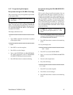
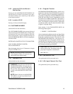
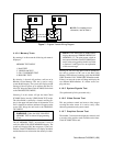
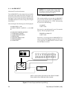
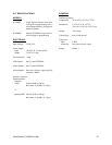
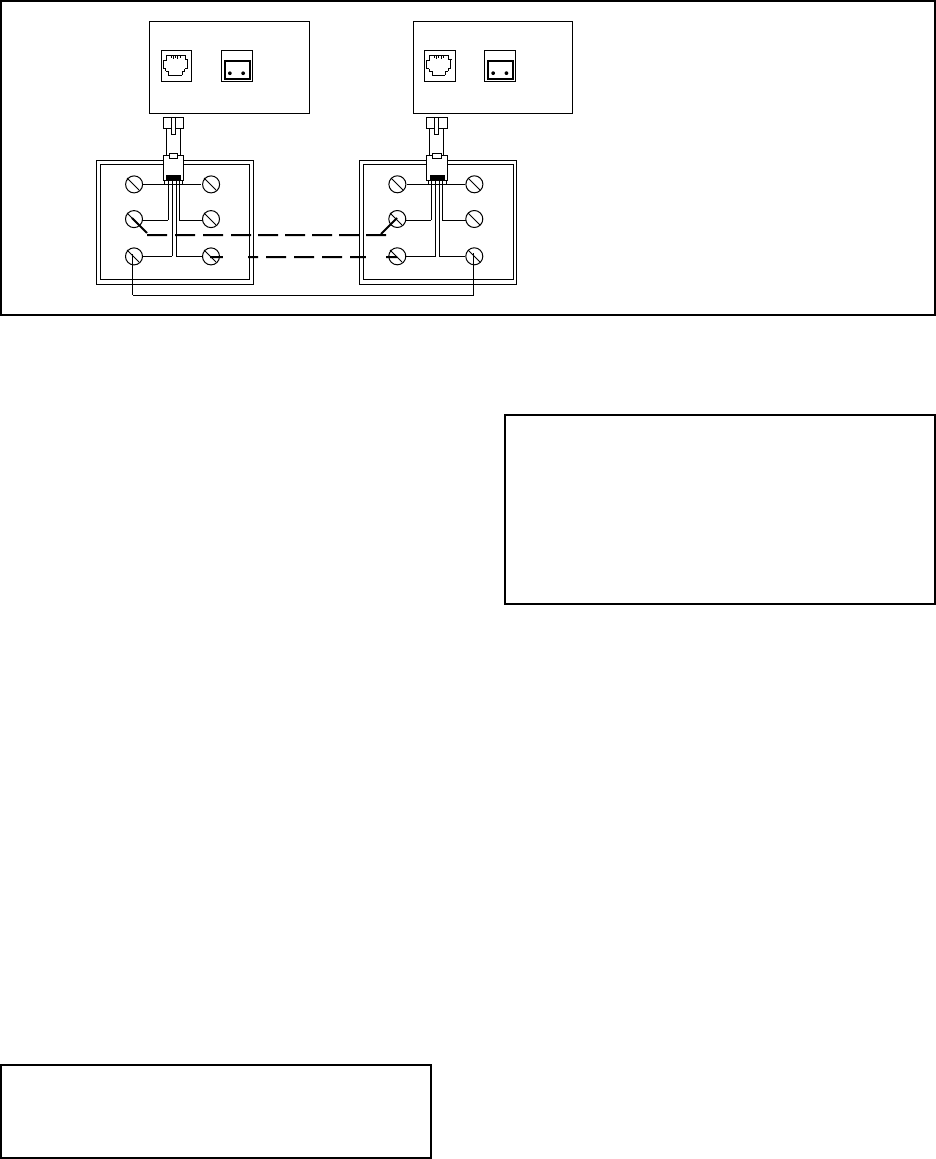
NOTE: For complete pin-out
information, refer to Table 3.
Data
In
Alarm
Out
Data
In
Alarm
Out
BL
BK
RD
WH
YL
GR
Figure 7. Program Transfer Wiring Diagram
BL
BK
RD
WH
YL
GR