Pelco Manual C1000M-B (1/96) 5
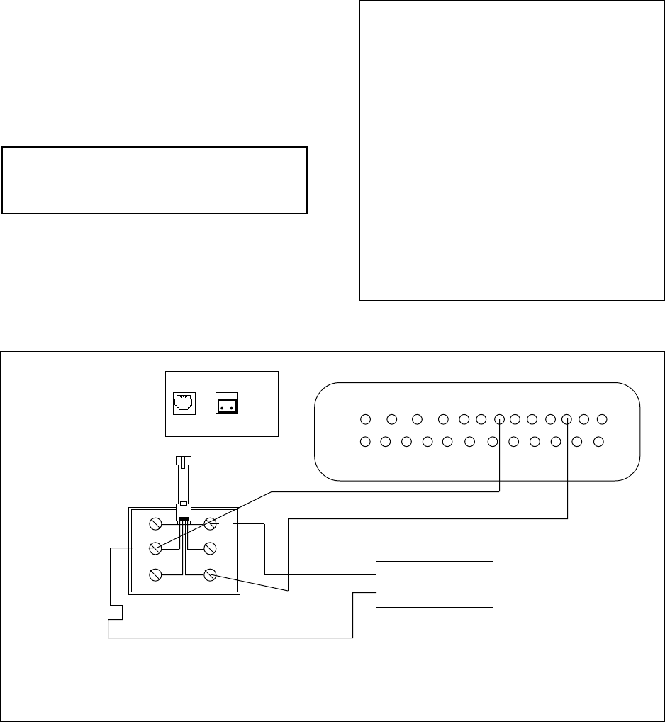
Figure 4. Printer Output and Alarm Input Wiring
3. Connect the data cable from the register interface
cable (or PIM) to “DATA IN” on the Inter-Check
ICI1000S, using the ICI1000WK and 18 gauge, 2-
conductor shielded cable (see Figure 1).
4. If using alarms, attach a 22-gauge, 2-conductor
shielded cable from the “ALARM OUT” of the
Inter-Check ICI1000S Series unit to your VCR,
switcher, or other alarmable device.
5. Plug the power supply for the Inter-Check
ICI1000S Series unit into a 120 VAC outlet.
6. Use the keypad on top of, or inside, the ICI1000S
chasis to set the standard PIM defaults. Press ENT,
6, 8 and then ESC to return to monitoring mode.
This step is required for all ICI1000S systems (re-
fer to Figure 4).
NOTE: ICI1000SI models have an internal
keypad; ICI1000SE models have an external
keypad.
7. Set the dip switches on the front of the ICI1000PIM
to match the setting for your register model num-
ber. Use the ICI1000PIM switch settings located
in the ICI1000PIM manual or Appendix B of this
manual. If your register does not require an
ICI1000PIM, disregard this step.
NOTE: A serial printer used with the Inter-Check ICI1000S
Series must be set at 1200 baud, 8 bits, no parity.
Alarm
Contact
Data
In
Alarm
Out
13 12 11 10 9 8 7 6 5 4 3 2 1
25 24 23 22 21 20 19 18 17 16 15 14
8. Plug the power supply for the ICI1000PIM into a
120 VAC outlet. The monitor should now display
the register model number.
9. If using the auxiliary print feature, and/or alarm
inputs, follow the wiring diagram in Figure 4 for
proper installation.
NOTE: The monitor should now show the ini-
tialization message shown below.
Pelco
INTER-CHECK/S VER X.X
ROM CHECK = YYYY
CALC. ROM CHECK = YYYY
SYSTEM BEING INITIALIZED!
MM VER. Z.Z
(register model # displayed here)
NOTE: If you do not receive this message,
refer to the troubleshooting guide in Section 5.0.
If your installation does not require the use of
an ICI1000PIM, the register model number will
not appear.
BL
YL
GR
WH
BK
RD
