


22 Pelco Manual C1000M-B (1/96)
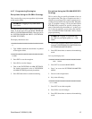
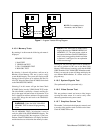
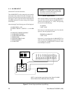
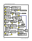
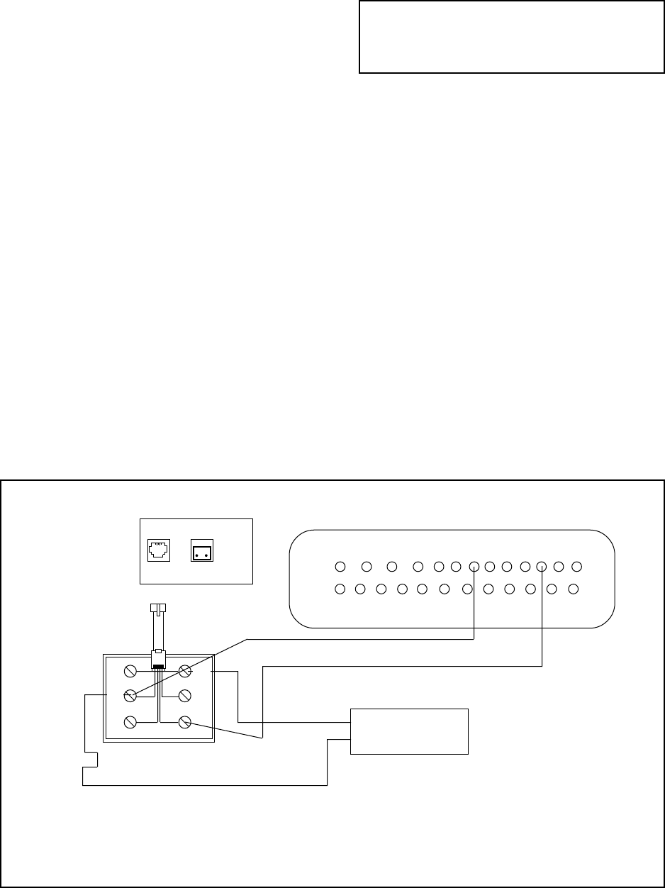
Figure 8. Printer Output and Alarm Input Wiring
4.11 ALARM INPUT
(Selection #7 from the main menu)
The ALARM INPUT can be connected to any normally
open (open loop) alarm device that can trigger a clo-
sure for at least one-half second. Once an alarm is valid,
the trigger is reset to open and will not detect the next
alarm until timeout. For correct wiring, refer to Figure
8 and Table 3.
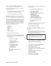
After selecting #7, the following text will be displayed:
ALARM DWELL : 6/D1
ALARM IN DWELL : 0/OFF/V1 = =>ALARM
IN
ALARM INPUT PROGRAM MENU
1. ALARM INPUT ON/OFF
2. ALARM TRIGGER DWELL
3. SCREEN LINK
4. AUXILIARY PRINT LINK
5. SCREEN HOMING
6. ALARM TEXT
NOTE: For a complete table of status label
descriptions used in the Inter-Check ICI1000S
Series menu system refer to Table 2.
4.11.1 Alarm Input On/Off
This selection enables you to turn the ALARM INPUT
on or off. You can also route an ALARM INPUT ex-
ception to the output port (i.e., VCR). After pressing
#1 you will see the following:
ALARM IN
1=OFF 2=ON
Press one (1) to turn the input off, or two (2) to turn the
input on. The next prompt will read:
TRIGGER ALARM OUT
1=OFF 2=ON
Select one (1) to not trigger the ALARM OUTPUT on
when an alarm from the input is received. Select two
(2) to trigger the ALARM OUTPUT when an alarm
from the input is received.
NOTE: A serial printer used with the Inter-Check ICI1000S
Series must be set at 1200 baud, 8 bits, no parity.
Alarm
Contact
Data
In
Alarm
Out
13 12 11 10 9 8 7 6 5 4 3 2 1
25 24 23 22 21 20 19 18 17 16 15 14
BL
YL
GR
WH
BK
RD