


32 Pelco Manual C1000M-B (1/96)
Installation instructions for configuring the ICI1000PIM
interface module are provided under separate cover in
manual C1005M-D.
If for some reason this manual is not readily available,
refer to the following section to configure the switch
settings on the PIM interface module, if applicable to
your installation.
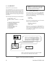
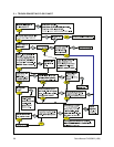
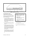
DESCRIPTION
The following describes the DIP switch settings for
banks #1 and #2 on the ICI1000PIM interface module
(refer to Figure 9).
SWITCH BANK #1
The switches in this bank serve several different
purposes. Some basic features include Polling or Non-
polling selections, PIM addressing, clock signal
manipulation and ICI1000PIM graphics mode select.
Switch 1 Selects either a non-inverting or
inverted clock signal. The position
of this switch will vary between
registers. The switch setting varies
depending on the cash register
selected in the register decode list for
SWITCH BANK 2.
Switch 2 Selects either Polling or Non-polling
operation. Polling mode is used only
with the ICI3000P unit (Party-line
configuration) and is defined with a
[–] switch setting. Non-polling mode
should be selected when using Pelco’s
ICI2000D or ICI1000S series products
(stand-alone configuration). This
mode is defined with a [+] switch
setting.
Switch 3 This is a dual function switch
depending on the register type used.
In dot matrix cash register
applications, this switch selects either
NORMAL [–] or PIM GRAPHICS
[+] mode. Other applications will
choose between either receipt or
journal information for monitor
display. Function of this switch are
shown on the page 3. This switch is
normally in the CLOSED [–]
position.
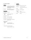
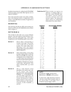
APPENDIX B. ICI1000PIM SWITCH SETTINGS
Switches 4-8 These switches are used to set
addresses of multiple PIM’s in a
Party-line system (ICI3000P unit).
The address selected normally
coincides with the actual cash
register number. The appropriate
switch settings for corresponding
PIM addresses are shown below.
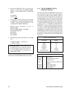
NOTE:
[–] indicates an UP switch position
[+] indicates a DOWN switch position
In other words, a [–] means that you need to
slide the switch towards the [–] position on
the switch. Refer to the Figure 9 for a
definition of [–] and [+] positions.
SWITCH # POLLING PIM ADDRESS
45678 (PIM #)
– –––– 1
–––– + 2
––– + – 3
–––+ + 4
–– + –– 5
– – + – + 6
– – + + – 7
– – + + + 8
– + – – – 9
– + – – + 10
– + – + – 11
– + – + + 12
– + + – – 13
– + + – + 14
– + + + – 15
– + + + + 16
+ –––– 17
+ – – – + 18
+ – – + – 19
+ – – + + 20
+ – + – – 21
+ – + – + 22
+ – + + – 23
+ – + + + 24
+ + – – – 25
+ + – – + 26
+ + – + – 27
+ + – + + 28
+ + + – – 29
+ + + – + 30
+ + + + – 31
+ + + + + 32