Pelco Manual C1000M-B (1/96) 3
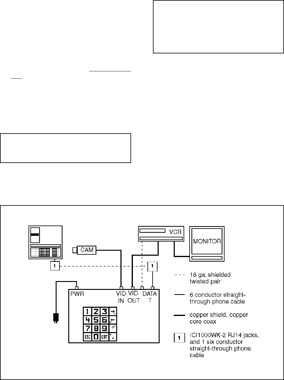
Figure 1. Basic ICI1000S Configuration Wiring Diagram
3.0 INSTALLATION
To begin installation, refer to the following instructions
and Figures 1 and 2.
3.1 INSTALLING INTERFACE CABLE
1. Install interface cable and PIM (if applicable) into
the cash register according to the instructions sup-
plied with your interface cable. Do not power up
PIM .
2 Install an 18 gauge, two-conductor shielded cable
between the interface cable/PIM and the ICI1000S
unit using the ICI1000WK (wiring kit) supplied
with your ICI1000S (refer to Figures 2 and 3). This
kit contains two RJ14 phone jacks and one straight-
through six conductor cable.
WARNINGS: Do not power up the Inter-
Check ICI1000S Series unit until all other con-
nections have been made.
Only use the power supply supplied with the Inter-Check
ICI1000S Series unit. Other power supplies may damage
the unit.
NOTE: Do not mount the Inter-Check
ICI1000S Series unit until all connections are
made and programming is complete. Video ad-
justments on the bottom of the Inter-Check
ICI1000S Series may need to be accessible
during the initial set-up.
3.2 BASIC INSTALLATIONS
For basic installations, perform the following steps:
1. Connect the cable from your video camera to the
BNC labeled “VIDEO IN” on the Inter-Check
ICI1000S (refer to Figure 1). This normally comes
from your camera, splitter, switcher or quad. For
Coaxitron matrix installations, connect the cable
from the desired MONITOR OUTPUT to the BNC
labeled “VIDEO IN” on the Inter-Check unit.
2. Connect a cable from the BNC labeled “VIDEO
OUT” on the Inter-Check ICI1000S Series to the
video input of your video cassette recorder or
monitor.


