


8 IP-REACH USER MANUAL
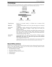
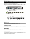
TR Series Physical Connections
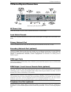
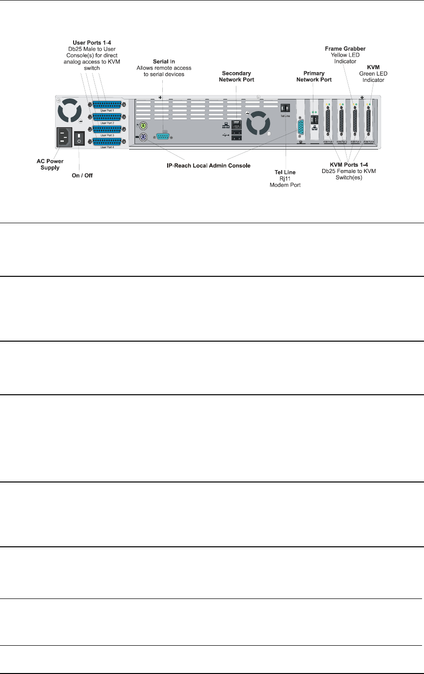
Back Panel of IP-Reach TR Series
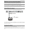
AC Power Line
Attach the included AC power cord to IP-Reach and into an AC Power Outlet.
Local Admin Console
Attach a PS/2 keyboard and multisync monitor to the indicated ports (see diagram above) in the back of IP-
Reach.
Primary Network Port
Connect a standard Ethernet cable from the network port to an Ethernet switch, hub, or router.
Secondary Network Port (optional)
Connect a standard Ethernet cable from the network port to an Ethernet switch, hub, or router. IP-Reach
automatically fails over to the secondary Network Port when the Primary Network Port is unavailable. See
Chapter 4: Administrative Functions, Network Configuration for instructions on enabling failover
Ethernet support.
KVM Input Ports
Connect the included CCP20 cable(s) from “KVM In” port to the KVM console of server or KVM switch
to be accessed remotely.
KVM Output / Local Access Console Ports (optional)
User ports “KVM Out” allow direct analog access to the server or KVM switch attached to corresponding
“KVM Input” ports. Connect the included CCP20F cable(s) from the ports labeled “User Port” to a PS/2
keyboard, PS/2 mouse, and multisync VGA monitor.
Note: Local Access Consoles can be attached to User Ports 1 through 4. Each Local Access Console will
view the KVM switch or server attached to the corresponding KVM Port. For example, the User Console
attached to User Port 1 will view the KVM switch or server attached to KVM Port 1. The User Console
attached to User Port 2 will view the KVM switch or server attached to KVM Port 2, and so on.
Telephone Line Port (optional)
IP-Reach TR Series models feature an integrated modem for remote access when the LAN/WAN is
unavailable. Use the included telephone cable to connect the port labeled “Tel Line” to an analog telephone
jack.