


Theory of Operation
13
3 Theory of Operation
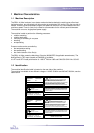
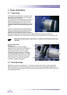
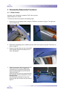
3-1 Control Knob
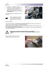
The Control Knob (see figure 1) is located on the
right hand side of the laminator and is operated
from the front of the machine.
The Control Knob can be operated by pushing it in
approximately 6mm (1/4”) to the left. Once the
knob has disengaged from the stop, it may be
rotated forward or backward (clockwise or counter-
clockwise, viewed from the right hand side of the
unit).
Continue to rotate the knob until the desired nip
setting corresponds with the indicator window at
the base of the knob. Inside the window, the
possible rotation directions are shown. Select the
value that corresponds to the thickness of the material you will be using with the machine.
Releasing the knob so that it moves back to the right and clicks into place will set the rollers for use.
Select the next lower value in case there is no match for the thickness of the used
substrate.
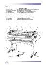
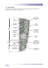
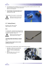
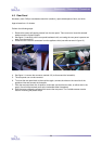
Internal functionality
See figure 2.
Inside the machine, a rod is mounted
between the left- and right-hand framesheets.
The knob is mounted on the rod; it allows
axial movement, but no radial movement.
The knob is provided with a pin (1), that falls
in the indents (2) of a bracket (3). The same
rod is provided with an eccentric (4) on either
side of the machine. These eccentrics push
or pull the arms (5), where the top roller is
mounted in, upward or downward.
3-2 Roller Nip settings
Whenever you mount onto a board, etc., it is important to adjust the rollers to create a gap nearly
equal to the thickness of the board being used. This is done so that anything passing between the
rollers will receive the right amount of pressure and prevent damage to the rubber surface of the roller
(and possibly the board).
1
2
3
4
5
fig. 1
fig. 2