


Disassembly / Reassembly Procedures
17
4 Disassembly/Reassembly Procedures
4-1 Plastic Covers
Necessary tools: hexalobular screwdriver TX25, Allen key 4mm.
Approximate time: 5 minutes
To remove the side covers, perform the following steps:
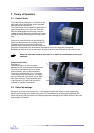
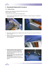
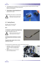
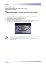
1. Remove the two self-tapping screws, using the TX25 driver, as shown in figure 4. The right hand
cover is shown here.
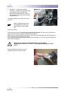
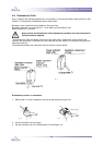
2. Remove the self-tapping screw, situated at the rear side of the machine, using the TX25 driver, as
shown in figere 5.
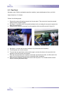
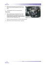
3. Remove, using the Allen key 4mm, the two M5
socket screws, situated at the bottom of the
cover. See figure 6.
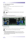
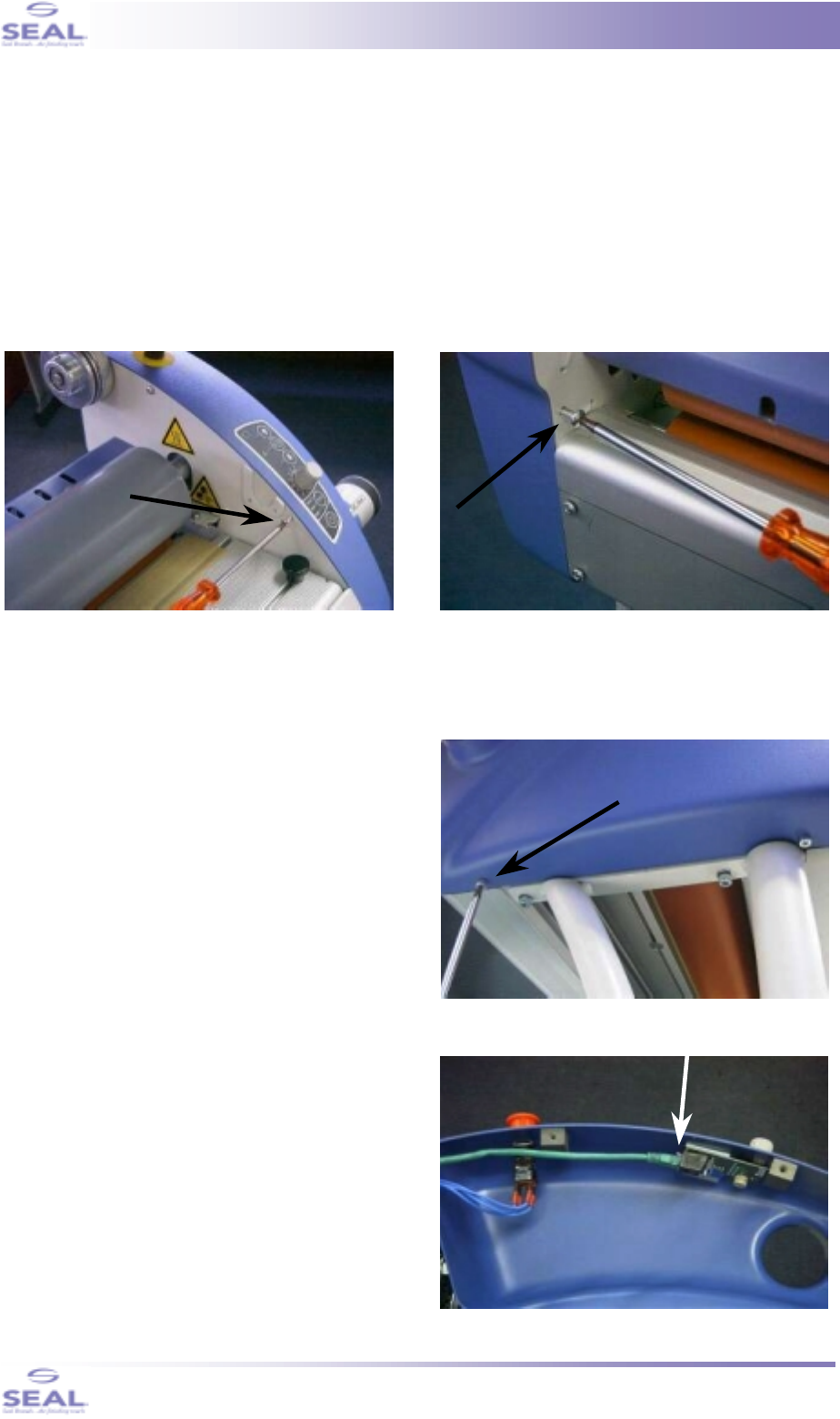
4. Carefully remove the right hand cover from the
frame of the machine. Now, a patchcable
connected to the controlpanel PCB and the
wires from the emergency stop will become
visible (see figure 7).
Hold the cover with one hand, whilst removing
the patchcable and the contactblock from the
emergency stop.
Push the little pin downward on top of the
socket and pull the connector out (see arrow in
figure 7).
fig. 4
fig. 5
fig. 6
fig. 7