


Adjustment Procedures
25
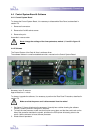
5 Adjustment Procedures
5-1 Laminating Pressure
Note:
To perform the following adjustments, it is necessary to remove both plastic side covers first.
See Section 4-1: Disassembly / Reassembly Plastic Side Covers.
There are two ways to adjust the laminating pressure:
1. Adjustment using load cells and display unit.
2. Adjustment using Heat Sensitive Film (JetGuard 5mil or Thermashield 5mil).
This procedure is preferred if the adjustment has to be done in the field, at the site of
the end-user.
Both ways need the following necessary tools: 10mm open-ended spanner, small flat-head
screwdriver, Allen key 3 mm.
Approximate time: 15 minutes.
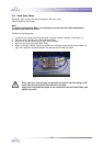
5-1-1 Adjustment using Load Cells and Display Unit
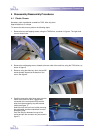
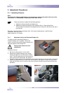
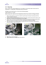
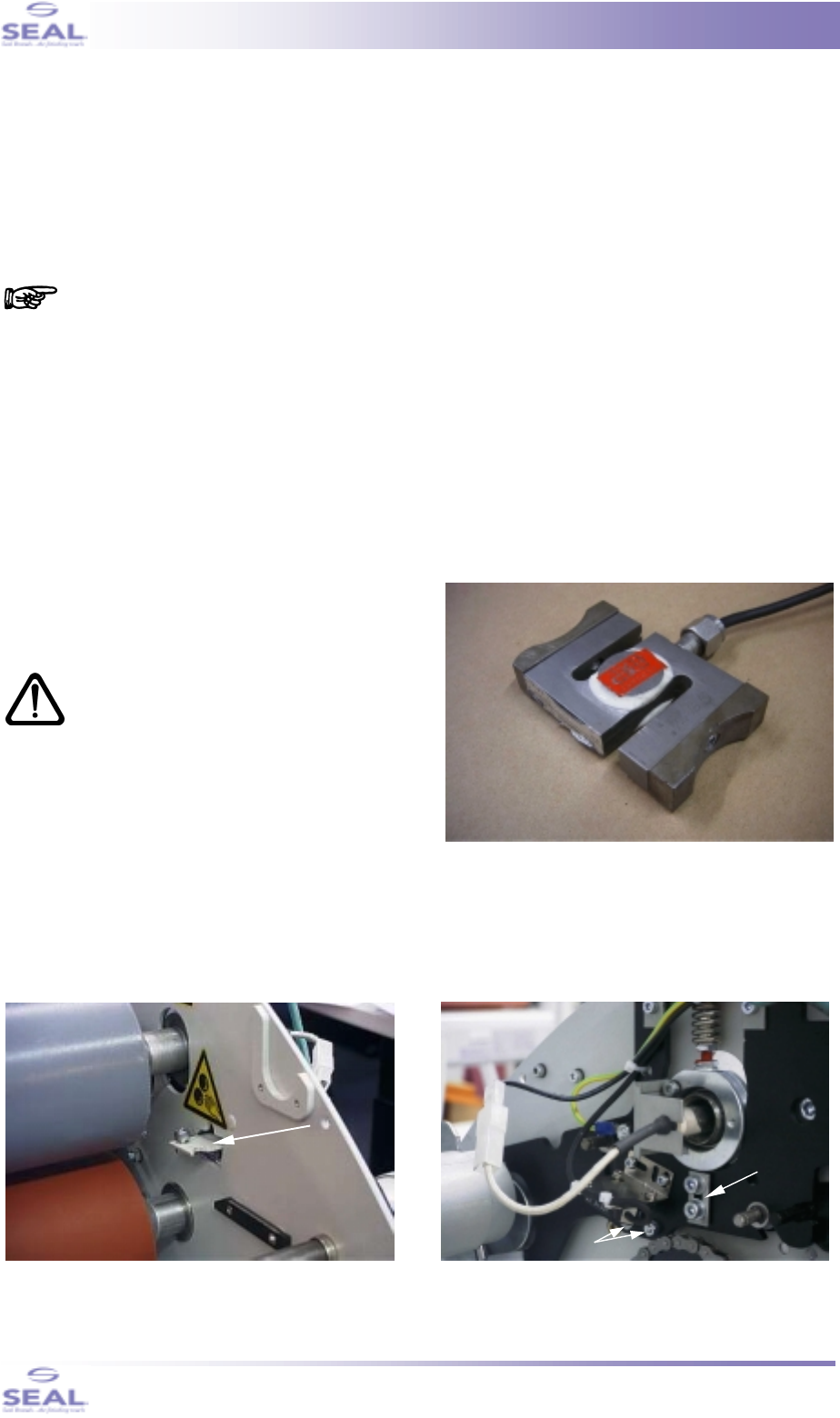
To adjust or set the laminating pressure, a
Pressure Display Unit is required. These units
come in various sizes and/or shapes; however, the
load cells typically look like figure 21.
The top roller must be at room
temperature!
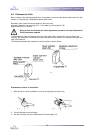
Proceed as follows:
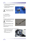
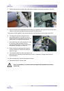
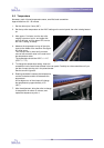
1. Set the nip setting knob to 10 mm (3/8”).
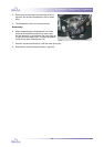
2. Remove the support brackets for the Image
Guide (see figure 22, the RH bracket is shown
here). The two bolts that have to be removed in
order to remove the RH bracket, are shown in
figure 23 (in later versions of the machine the way these bolts and nuts are mounted, is reversed).
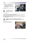
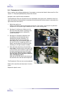
3. Loosen the adjustment strip on either side of the machine. See figure 23, right-hand strip shown.
Note that the strips must not touch the top roller bearing housing during the pressure adjustment
procedure.
fig. 22
fig. 21
fig. 23
adjustment
strip
remove
bolts