Adjustment Procedures
33
5-7 Image Guide
To perform the following adjustment, it is necessary to remove both plastic side covers first. See
Section 4-1: Disassembly/Reassembly Plasic Side Covers.
Necessary tools: allen key 3mm, gauge 2mm.
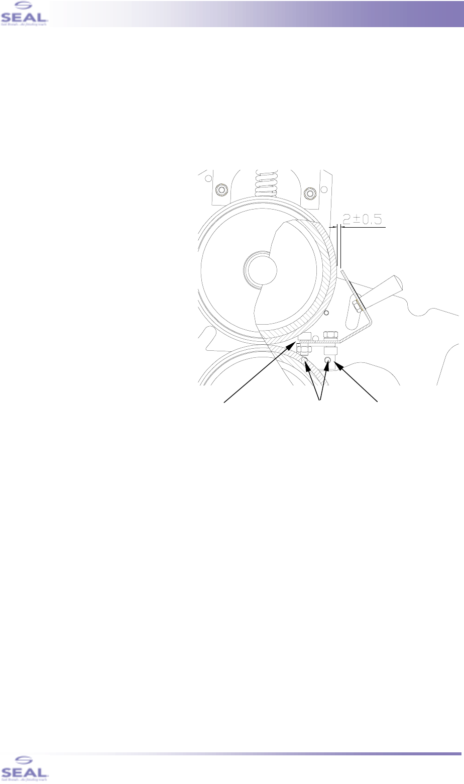
The distance between the upper edge of the Image Guide and the roll surface must be 2±0.5mm
(0.0787±0.0196 inch), see figure 37.
1. To adjust the Image Guide, it is
necessary to position it in front of the
top roller, onto the two support
brackets (see arrow #1).
2. Slide the Image Guide all the way
towards the roll; make sure that the
front edge of the Guide is under the
bolt mounted in the support bracket
(see arrow #2).
3. If necessary, loosen the two socket
screws (arrows #3), that hold the
support bracket, half a turn. Perform
this at either side of the machine.
4. Reposition the support brackets until
the previously mentioned distance of
2 mm has been achieved.
Thighten the socket screws and
reassemble the plastic covers.
1
2
3
fig. 37


