


Adjustment Procedures
26
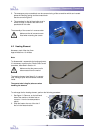
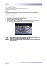
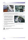
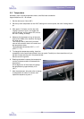
4. Position the load cells at either side of the rollers, between the journals, as shown in figure 24.
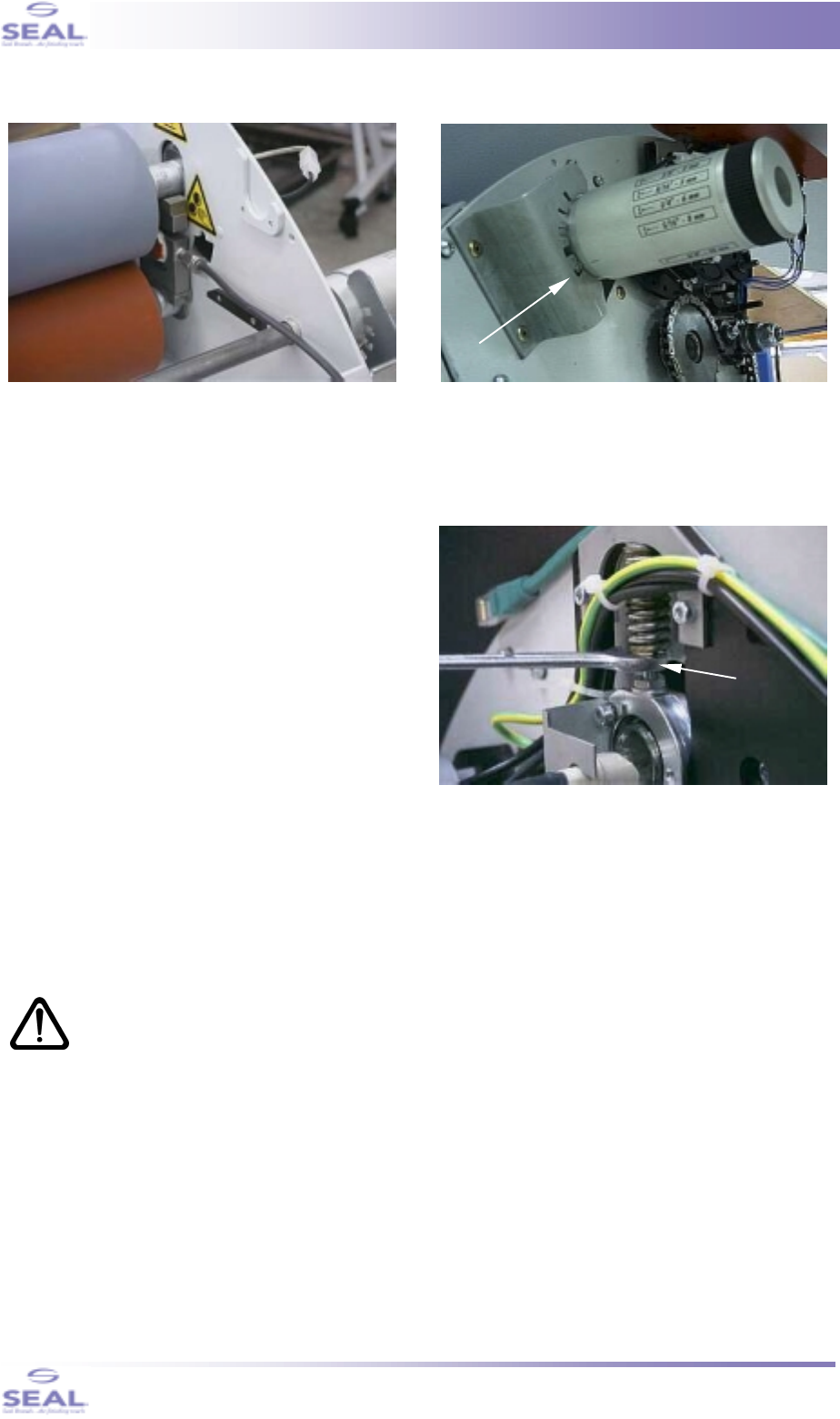
5. Push and rotate the nip adjustment knob until the pin, mounted in the knob, falls into the last notch
(relative to top) from the indent bracket (see figure 25, white arrow).
The pressure will be applied to the pressure sensors, and the pressure can be read on the PDU.
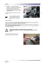
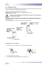
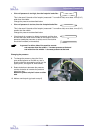
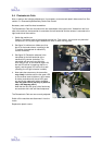
6. To change the pressure, place the 10mm
open-ended spanner on the M6 nut, that is
directly under the compression spring (so, the
upper jamnut, see figure 26, white arrow).
7. On the left-hand side of the machine, it is best
to remove the blue connector from the
overtemperature switch, to ease access with
the spanner. See figure 10, arrow #1.
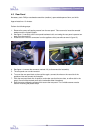
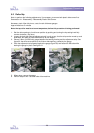
8. Rotate clockwise to decrease the pressure,
counter-clockwise to increase the pressure
(seen from top).
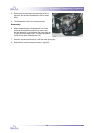
9. The pressure readout for each load cell (so, for
either side of the machine) should be 55 kgf (121 lbf). If necessary, change these values as
described above.
10. After the adjustment, remove the pressure sensors.
11. Assemble all parts in reverse order.
Now, it is mandatory to continue with the Image Guide Adjustment procedure,
section 5.6
fig. 24 fig. 25
fig. 26