


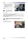
Disassembly / Reassembly Procedures
23
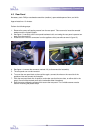
4-6 Photoelectric Cells
Note: to perform the following adjustments, it is necessary to remove both plastic side covers first. See
section 4.1: Disassembly / Reassembly plastic side covers.
Necessary tools: small flat head screwdriver, Allen key 3mm
Necessary materials: two tie-wraps (2.5 – 3 mm wide), per Photoelectric Cell.
Approximate time: 10 minutes.
Note: perform the Photoelectric Cells Adjustment procedure once the Photoelectric
Cell(s) have been replaced.
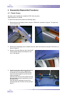
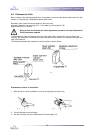
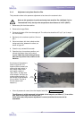
The Photoelectric Cells are fitted on the arms of the upper roller. Viewed from the front-side of the
machine, the transmitter is mounted at the left-hand side and the reciever is mounted at the right-hand
side of the machine.
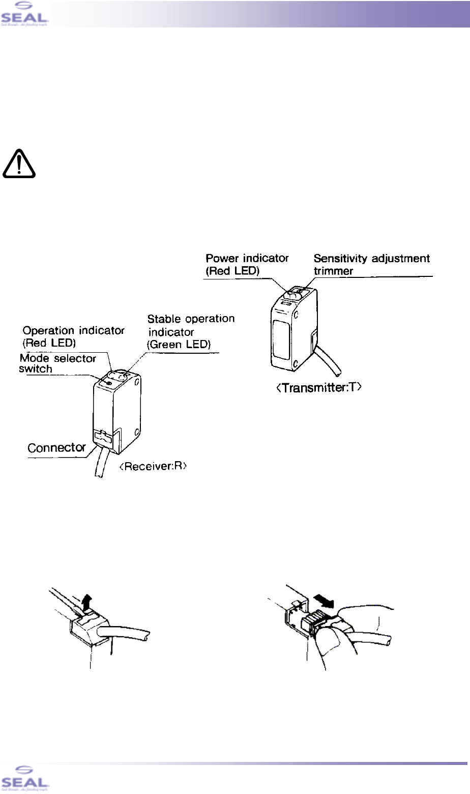
The difference between the transmitter and the receiver is shown below.
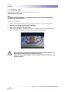
Disassembly reciever or transmitter.
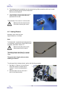
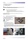
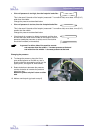
1. With the aid of a small screwdriver, remove the springclip (see figure 18).
2. Cut and discard the two tie-wraps.
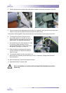
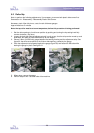
3. Pull the connector out of the Photoelectric Cell (see figure 19).
fig. 17
fig. 18
fig. 19