


Adjustment Procedures
31
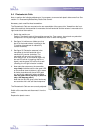
5-4 Photoelectric Cells
Note: to perform the following adjustments, it is necessary to remove both plastic side covers first. See
section 4-1: Disassembly/Reassembly Plastic Side Covers.
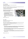
Necessary tools: small flat-head screwdriver.
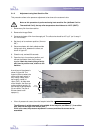
The Photoelectric Cells are mounted on the arm assemblies of the upper roller. Viewed from the front-
side of the machine, the transmitter is mounted at the left-hand side and the reciever is mounted at the
right-hand side of the machine.
1. Switch the machine on.
Caution! The electric parts of the machine are now live. From now on, do not touch any electrical
components. Do not place fingers between the chain or other moving parts.
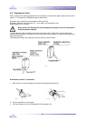
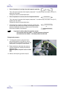
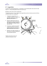
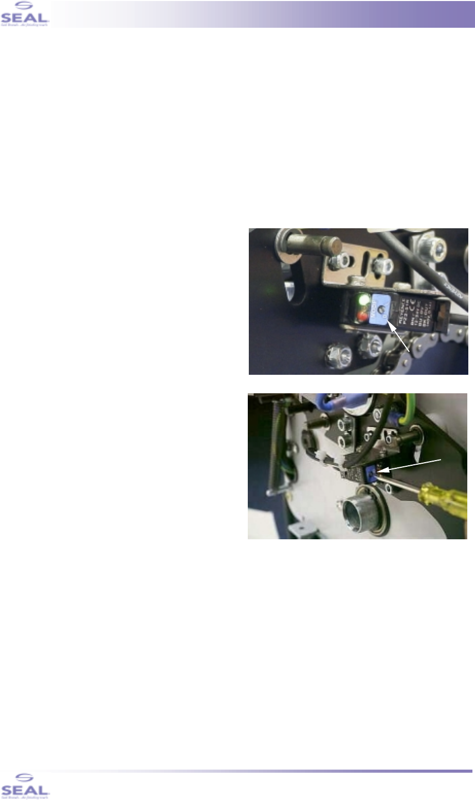
2. See figure 34, white arrow. Make sure, that
the slit in the mode selector is pointing to the
‘D’ position (the setscrew is rotated fully
counter-clockwise).
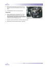
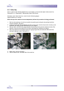
3. See figure 35. Rotate the setscrew in the
transmitter (at the left-hand side of the
machine) fully counter-clockwise. The
transmitter will now emit very little light.
As a result of this, on the receiver (figure 34)
the red LED will be lit (meaning: there’s no
signal), and the green LED will be lit as well
(meaning: the ‘no-light’ situation is stable)
4. Now rotate the setscrew on the transmitter
very slowly clockwise until the the green LED
on the reciever starts to fade out, next rotate a
bit further clockwise until the red LED goes
out, and finally rotate a bit further clockwise
until the green LED is just fully lit (which is
only a few degrees more!).
Note that the red LED gives a faint flash every
two seconds: this is the self-check sequence.
The Photoelectric Cells are now correctly adjusted.
Switch off the machine and disconnect it from the
mains.
Replace the plactic covers.
fig. 34
fig. 35