Si53xx-RM
Rev. 0.5 103
7.14. Serial Microprocessor Interface (SPI)
When configured in SPI control mode (CMODE = H), the control interface to the device is a 4-wire interface
modeled after commonly available microcontroller and serial peripheral devices. The interface consists of a clock
input (SCLK), slave select input (SSb), serial data input (SDI), and serial data output (SDO). In addition, an output
interrupt (INT) is provided with selectable active polarity (determined by INT_POL bit).
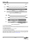
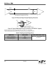
Data is transferred a byte at a time with each register access consisting of a pair of byte transfers. Figure 36 and
Figure 37 illustrate read and write/set address operations on the SPI bus, and AC SPEC gives the timing
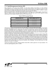
requirements for the interface. Table 55 shows the SPI command format.
The first byte of the pair is the instruction byte. The “Set Address” command writes the 8 bit address value that will
be used for the subsequent read or write. The “Write” command writes data into the device based on the address
previously established and the “Write/Address Increment” command writes data into the device and then
automatically increments the register address for use on the subsequent command. The “Read” command reads
one byte of data from the device and the “Read/Address Increment” reads one byte and increments the register
address automatically. The second byte of the pair is the address or data byte.
As shown in Figure 36 and Figure 37, SSb should be held low during the entire two byte transfer. Raising SSb
resets the internal state machine; so, SSb can optionally be raised between each two byte transfers to guarantee
the state machine will be reinitialized. During a read operation, the SDO becomes active on the falling edge of
SCLK and the 8-bit contents of the register are driven out MSB first. The SDO is high impedance on the rising edge
of SS. SDI is a “don’t care” during the data portion of read operations. During write operations, data is driven into
the device via the SDI pin MSB first. The SDO pin will remain high impedance during write operations. Data always
transitions with the falling edge of the clock and is latched on the rising edge. The clock should return to a logic
high when no transfer is in progress.
The SPI port supports continuous clocking operation where SSb is used to gate two or four byte transfers. The
maximum speed supported by SPI is 10 MHz.
Table 55. SPI Command Format
Instruction(BYTE0) Address/Data[7:0](BYTE1)
00000000—Set Address AAAAAAAA
01000000—Write DDDDDDDD
01100000—Write/Address Increment DDDDDDDD
10000000—Read DDDDDDDD
10100000—Read/Address Increment DDDDDDDD


