


40 | CHAPTER 4 – REMOTELY MANAGING YOUR INTERACTIVE WHITEBOARD
SYSTEM
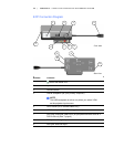
Connecting Your Room Control System
to the SMART UF65 or SMART UF65w
Projector
By connecting a computer or room control system to the SMART UF65 or SMART
UF65w projector’s RS-232 serial interface, you can select video inputs, start up or
shut down your interactive whiteboard system and request information such as
projector lamp use, current settings and network addresses.
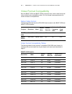
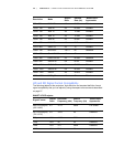
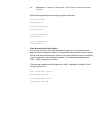
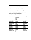
Pin Configuration on the Projector’s RS-232 Connector
The following table provides the pin configuration on the SMART UF65 or
SMART UF65w projector. This pin configuration follows a three-wire connection so
that a straight-through male to female RS-232 serial cable connects to the projector’s
serial interface in the following arrangement:
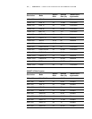
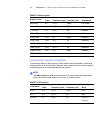
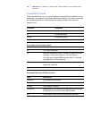
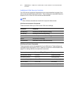
Serial Interface Settings
The SMART UF65 or SMART UF65w projector’s serial interface acts as a Data
Communications Equipment (DCE) device and its settings can’t be configured.
You must configure your computer’s serial communication program (such as
Microsoft® HyperTerminal) or your room control system’s serial communication
settings with the following values:
Pin Number Projector’s Female RS-232 Connector
2 Transmit
3 Receive
5 Signal Ground
Setting Value
Data Rate 19.2 kbps
Data Bits 8
Parity None
Stop Bits 1
Flow Control None