BioOptix™ 10
Section 2 Installation
2-6
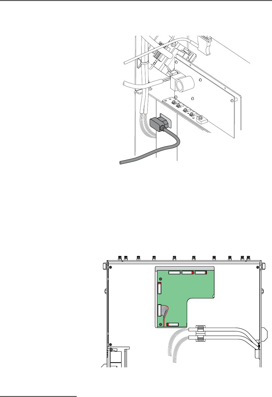
7. Plug the black power cord from the pump module into the
receptacle at the lower part of the column module (Figure
2-8).
Figure 2-8 AC power connection from pump module
8. Before completing the remaining cable connections, replace
the back metal plate on the column module. The openings
in the plate will fit around the connections made in steps 3
through 7. Secure the plate with the four screws (Figure
2-3). Then, reattach the tubing to the retaining clips.
9. The remaining ribbon cable connections are routed from
the top of the pump module through the opening on the
back plate of the column module. Refer to Figure 2-9 and
complete the connections, matching the connector labels.
Figure 2-9 Ribbon cable connections
(top half of column module shown)
From
Pump
Module
P6
P12
Not
Used
P8 P11
Tubing to pump
module


