


Architecture
www.ti.com
2.5.5 Read and Write Operations in Select Strobe Mode
Select Strobe mode is the EMIF's second mode of operation. The SS mode is selected when the SS bit in
the asynchronous configuration register (ACFGn) is set to 1. In this mode, the EM_CS pin functions as a
strobe signal and is therefore only active during the strobe period of an access cycle.
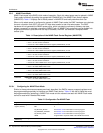
2.5.5.1 Asynchronous Read Operations (Select Strobe Mode)
An asynchronous read is performed when any of the requesters mentioned in Section 2.2 request a read
from the attached asynchronous memory. In the event that the read request cannot be serviced by a
single access cycle to the external device, multiple access cycles will be performed by the EMIF until the
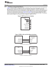
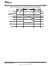
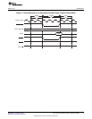
entire request is fulfilled. The details of an asynchronous read operation in Select Strobe mode are
described in Table 9 and an example timing diagram of a basic read operation is shown in Figure 6.
NOTE: During the entirety of an asynchronous read operation, the EM_WE and EM_RW pins are
driven high.
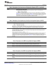
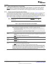
Table 9. Asynchronous Read Operation in Select Strobe Mode
Time Interval Pin Activity in Select Strobe Mode
Turnaround Once the EMIF receives a read request, the EMIF waits for the programmed number of turnaround cycles before
period proceeding to the setup period of the operation. The number of wait cycles is taken directly from the TA field of
the asynchronous configuration register (ACFGn). There are two exceptions to this rule:
• If the current read operation was directly proceeded by another read operation to the same CS space, no
turnaround cycles are inserted.
• If the current read operation was not directly proceeded by a read operation to the same CS space and the
TA field has been cleared to 0, one turnaround cycle will be inserted.
After the EMIF has waited for the turnaround cycles to complete, it proceeds to the setup period of the operation.
Start of setup At the beginning of the setup period:
period
• The setup, strobe, and hold values are set according to the R_SETUP, R_STROBE, and R_HOLD values
in ACFGn.
• The address pins EM_A and EM_BA become valid.
Start of strobe At the beginning of the strobe period:
period
• EM_CS and EM_OE fall at the start of the strobe period
Start of hold At the beginning of the hold period:
period
• EM_CS and EM_OE rise
• The EMIF samples the data on the EM_D bus
End of hold At the end of the hold period:
period
• The address pins EM_A and EM_BA become invalid
The EMIF may be required to issue additional read operations to a device with a small data bus width in order to
complete an entire word access. In this case, the EMIF immediately re-enters the setup period to begin another
operation without incurring the turnaround cycle delay. The setup, strobe, and hold values are not updated in this
case. If the entire word access has been completed, the EMIF returns to its previous state unless another
asynchronous request has been submitted. If this is the case, the EMIF instead enters directly into the
turnaround period for the pending read or write operation.
18
Asynchronous External Memory Interface (EMIF) SPRUEQ7C–February 2010
Submit Documentation Feedback
Copyright © 2010, Texas Instruments Incorporated