


Registers
www.ti.com
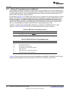
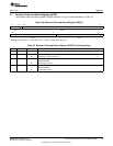
4 Registers
The external memory interface (EMIF) is controlled by programming its internal memory-mapped registers
(MMRs). Table 32 lists the memory-mapped registers for the EMIF. See the device-specific data manual
for the memory address of these registers. All other register offset addresses not listed in Table 32 should
be considered as reserved locations and the register contents should not be modified.
NOTE: The EMIF MMRs only support word (4 byte) accesses. Performing a byte (8 bit) or halfword
(16 bit) write to a register results in unknown behavior.
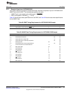
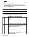
Table 32. External Memory Interface (EMIF) Registers
Offset Acronym Register Description Section
0 RCSR Revision Code and Status Register Section 4.1
4h AWCCR Asynchronous Wait Cycle Configuration Register Section 4.2
10h A1CR Asynchronous 1 Configuration Register (CS2 space) Section 4.3
14h A2CR Asynchronous 2 Configuration Register (CS3 space) Section 4.3
18h A3CR Asynchronous 3 Configuration Register (CS4 space) Section 4.3
1Ch A4CR Asynchronous 4 Configuration Register (CS5 space) Section 4.3
40h EIRR EMIF Interrupt Raw Register Section 4.4
44h EIMR EMIF Interrupt Mask Register Section 4.5
48h EIMSR EMIF Interrupt Mask Set Register Section 4.6
4Ch EIMCR EMIF Interrupt Mask Clear Register Section 4.7
60h NANDFCR NAND Flash Control Register Section 4.8
64h NANDFSR NAND Flash Status Register Section 4.9
70h NANDF1ECC NAND Flash 1 ECC Register (CS2 Space) Section 4.10
74h NANDF2ECC NAND Flash 2 ECC Register (CS3 Space) Section 4.10
78h NANDF3ECC NAND Flash 3 ECC Register (CS4 Space) Section 4.10
7Ch NANDF4ECC NAND Flash 4 ECC Register (CS5 Space) Section 4.10
48
Asynchronous External Memory Interface (EMIF) SPRUEQ7C–February 2010
Submit Documentation Feedback
Copyright © 2010, Texas Instruments Incorporated