


www.ti.com
Registers
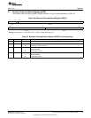
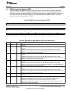
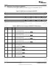
4.4 EMIF Interrupt Raw Register (EIRR)
The EMIF interrupt raw register (EIRR) is used to monitor and clear the EMIF’s hardware-generated
interrupts. The bits in EIRR are set when an interrupt condition occurs, regardless of the status of the
EMIF interrupt mask set register (EIMSR) and EMIF interrupt mask clear register (EIMCR). Writing a 1 to
a bit clears the bit and the corresponding bit in the EMIF interrupt mask register (EIMR). The EIRR is
shown in Figure 23 and described in Table 36.
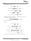
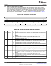
Figure 23. EMIF Interrupt Raw Register (EIRR)
31 16
Reserved
R-0
15 8
Reserved
R-0
7 6 5 4 3 2 1 0
Reserved WR3 WR2 WR1 WR0 Reserved AT
R-0 R/W1C-0 R/W1C-0 R/W1C-0 R/W1C-0 R-0 R/W1C-0
LEGEND: R/W = Read/Write; R = Read only; W1C = Write 1 to clear (writing 0 has no effect); -n = value after reset
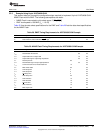
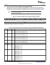
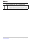
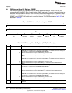
Table 36. EMIF Interrupt Raw Register (EIRR) Field Descriptions
Bit Field Value Description
31-6 Reserved 0 Reserved. The reserved bit location is always read as 0. If writing to this field, always write the default
value of 0.
5 WR3 Wait Rise. This bit is set to 1 by hardware to indicate that a rising edge on the EM_WAIT[5] pin has
occurred.
0 Indicates that a rising edge has not occurred on the EM_WAIT[5] pin. Writing a 0 has no effect.
1 Indicates that a rising edge has occurred on the EM_WAIT[5] pin. Writing a 1 will clear this bit and the
WRM3 bit in the EMIF interrupt mask register (EIMR).
4 WR2 Wait Rise. This bit is set to 1 by hardware to indicate that a rising edge on the EM_WAIT[4] pin has
occurred.
0 Indicates that a rising edge has not occurred on the EM_WAIT[4] pin. Writing a 0 has no effect.
1 Indicates that a rising edge has occurred on the EM_WAIT[4] pin. Writing a 1 will clear this bit and the
WRM2 bit in the EMIF interrupt mask register (EIMR).
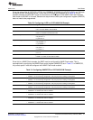
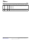
3 WR1 Wait Rise. This bit is set to 1 by hardware to indicate that a rising edge on the EM_WAIT[3] pin has
occurred.
0 Indicates that a rising edge has not occurred on the EM_WAIT[3] pin. Writing a 0 has no effect.
1 Indicates that a rising edge has occurred on the EM_WAIT[3] pin. Writing a 1 will clear this bit and the
WRM1 bit in the EMIF interrupt mask register (EIMR).
2 WR0 Wait Rise. This bit is set to 1 by hardware to indicate that a rising edge on the EM_WAIT[0] pin has
occurred.
0 Indicates that a rising edge has not occurred on the EM_WAIT[0] pin. Writing a 0 has no effect.
1 Indicates that a rising edge has occurred on the EM_WAIT[0] pin. Writing a 1 will clear this bit and the
WRM0 bit in the EMIF interrupt mask register (EIMR).
1 Reserved 0 Reserved. The reserved bit location is always read as 0. If writing to this field, always write the default
value of 0.
0 AT Asynchronous Timeout. This bit is set to 1 by hardware to indicate that during an extended
asynchronous memory access cycle the EM_WAITn pin did not go inactive within the number of cycles
defined by the MEWC field in the asynchronous wait cycle configuration register (AWCCR).
0 Indicates that an asynchronous timeout has not occurred. Writing a 0 has no effect.
1 Indicates that an asynchronous timeout has occurred. Writing a 1 will clear this bit and the ATM bit in
the EMIF interrupt mask register (EIMR).
53
SPRUEQ7C–February 2010 Asynchronous External Memory Interface (EMIF)
Submit Documentation Feedback
Copyright © 2010, Texas Instruments Incorporated