


Registers
www.ti.com
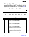
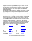
4.7 EMIF Interrupt Mask Clear Register (EIMCR)
The EMIF interrupt mask clear register (EIMCR) is used to disable the interrupts. If a bit is read as 1, the
corresponding bit in the EMIF interrupt mask register (EIMR) is set and an interrupt is generated when the
associated interrupt condition occurs. If a bit is read as 0, the corresponding bit in EIMR will always read 0
and no interrupts are generated when the corresponding interrupt condition occurs. Writing a 1 to the
WRMCLRn and ATMCLR bits disables each respective interrupt. The EIMCR is shown in Figure 26 and
described in Table 39.
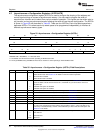
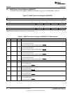
Figure 26. EMIF Interrupt Mask Clear Register (EIMCR)
31 16
Reserved
R-0
15 8
Reserved
R-0
7 6 5 4 3 2 1 0
Reserved WRMCLR3 WRMCLR2 WRMCLR1 WRMCLR0 Reserved ATMCLR
R-0 R/W1C-0 R/W1C-0 R/W1C-0 R/W1C-0 R-0 R/W1C-0
LEGEND: R/W = Read/Write; R = Read only; W1C = Write 1 to clear (writing 0 has no effect); -n = value after reset
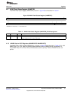
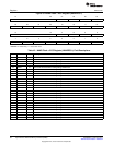
Table 39. EMIF Interrupt Mask Clear Register (EIMCR) Field Descriptions
Bit Field Value Description
31-6 Reserved 0 Reserved. The reserved bit location is always read as 0. If writing to this field, always write the default
value of 0.
5 WRMCLR3 Wait Rise Mask Clear. This bit determines whether or not the wait rise interrupt is enabled. Writing a 1
to this bit clears this bit and the WRMSET3 bit in the EMIF interrupt mask set register (EIMSR), and
disables the wait rise interrupt. To set this bit, a 1 must be written to the WRMSET3 bit in EIMSR.
0 Indicates that the wait rise interrupt is disabled. Writing a 0 has no effect.
1 Indicates that the wait rise interrupt is enabled. Writing a 1 clears this bit and the WRMSET3 bit in
EIMSR.
4 WRMCLR2 Wait Rise Mask Clear. This bit determines whether or not the wait rise interrupt is enabled. Writing a 1
to this bit clears this bit and the WRMSET2 bit in the EMIF interrupt mask set register (EIMSR), and
disables the wait rise interrupt. To set this bit, a 1 must be written to the WRMSET2 bit in EIMSR.
0 Indicates that the wait rise interrupt is disabled. Writing a 0 has no effect.
1 Indicates that the wait rise interrupt is enabled. Writing a 1 clears this bit and the WRMSET2 bit in
EIMSR.
3 WRMCLR1 Wait Rise Mask Clear. This bit determines whether or not the wait rise interrupt is enabled. Writing a 1
to this bit clears this bit and the WRMSET1 bit in the EMIF interrupt mask set register (EIMSR), and
disables the wait rise interrupt. To set this bit, a 1 must be written to the WRMSET1 bit in EIMSR.
0 Indicates that the wait rise interrupt is disabled. Writing a 0 has no effect.
1 Indicates that the wait rise interrupt is enabled. Writing a 1 clears this bit and the WRMSET1 bit in
EIMSR.
2 WRMCLR0 Wait Rise Mask Clear. This bit determines whether or not the wait rise interrupt is enabled. Writing a 1
to this bit clears this bit and the WRMSET0 bit in the EMIF interrupt mask set register (EIMSR), and
disables the wait rise interrupt. To set this bit, a 1 must be written to the WRMSET0 bit in EIMSR.
0 Indicates that the wait rise interrupt is disabled. Writing a 0 has no effect.
1 Indicates that the wait rise interrupt is enabled. Writing a 1 clears this bit and the WRMSET0 bit in
EIMSR.
1 Reserved 0 Reserved. The reserved bit location is always read as 0. If writing to this field, always write the default
value of 0.
58
Asynchronous External Memory Interface (EMIF) SPRUEQ7C–February 2010
Submit Documentation Feedback
Copyright © 2010, Texas Instruments Incorporated