


www.ti.com
Registers
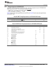
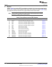
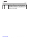
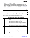
Table 34. Asynchronous Wait Cycle Configuration Register (AWCCR) Field Descriptions (continued)
Bit Field Value Description
17-16 CS2_WAIT 0-3h EM_WAIT[5:2] pin map for chip select 2. By default, the EM_WAIT[2] pin is used for chip select 2.
0 EM_WAIT[2] pin is used.
1h EM_WAIT[3] pin is used.
2h EM_WAIT[4] pin is used.
3h EM_WAIT[5] pin is used.
15-8 Reserved 0 Reserved
7-0 MEWC 0-FFh Maximum extended wait cycles. The EMIF will wait for a maximum of (MEWC + 1) × 16 clock cycles
before it stops inserting asynchronous wait cycles and proceeds to the hold period of the access.
51
SPRUEQ7C–February 2010 Asynchronous External Memory Interface (EMIF)
Submit Documentation Feedback
Copyright © 2010, Texas Instruments Incorporated