


R_SETUP ) R_STROBE w
ǒ
t
ACC
(m) ) t
SU
Ǔ
t
cyc
* 1
R_SETUP ) R_STROBE ) R_HOLD w
t
RC
(m)
t
cyc
* 3
R_HOLD w
ǒ
t
H
* t
OH
(m)
Ǔ
t
cyc
* 1
TA w
t
COD
(m)
t
cyc
* 1
www.ti.com
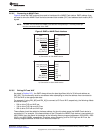
Use Cases
3.1.2 Meeting AC Timing Requirements for ASRAM
When configuring the EMIF to interface to ASRAM, you must consider the AC timing requirements of the
ASRAM as well as the AC timing requirements of the EMIF. These can be found in the data sheet for
each respective device. The read and write asynchronous cycles are programmed separately in the
asynchronous configuration register (ACFGn).
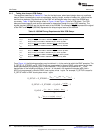
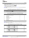
For a read access, Table 15 to Table 17 list the AC timing specifications that must be considered.
Table 15. EMIF Input Timing Requirements
Parameter Description
t
SU
Data Setup time, data valid before EM_OE high
t
H
Data Hold time, data valid after EM_OE high
Table 16. ASRAM Output Timing Characteristics
Parameter Description
t
ACC
Address Access time
t
OH
Output data Hold time for address change
t
COD
Output Disable time from chip enable
Table 17. ASRAM Input Timing Requirement for a Read
Parameter Description
t
RC
Read Cycle time
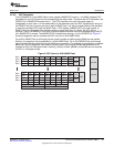
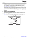
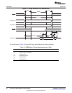
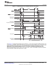
Figure 12 shows an asynchronous read access and describes how the EMIF and ASRAM AC timing
requirements work together to define the values for R_SETUP, R_STROBE, and R_HOLD.
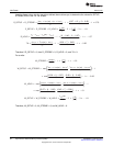
From Figure 12, the following equations may be derived. t
cyc
is the period at which the EMIF operates. The
R_SETUP, R_STROBE, and R_HOLD fields are programmed in terms of EMIF cycles where as the data
sheet specifications are typically given in nano seconds. This explains the presence of t
cyc
in the
denominator of the following equations. A minus 1 is included in the equations because each field in
ACFGn is programmed in terms of EMIF clock cycles, minus 1 cycle. For example, R_SETUP is equal to
R_SETUP width in EMIF clock cycles minus 1 cycle.
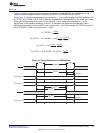
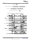
The EMIF offers an additional parameter, TA, that defines the turnaround time between read and write
cycles. This parameter protects against the situation when the output turn-off time of the memory is longer
than the time it takes to start the next write cycle. If this is the case, the EMIF will drive data at the same
time as the memory, causing contention on the bus. By examining Figure 12, the equation for TA can be
derived as:
31
SPRUEQ7C–February 2010 Asynchronous External Memory Interface (EMIF)
Submit Documentation Feedback
Copyright © 2010, Texas Instruments Incorporated