


MII-Enhanced Interrupt Event Feature
7-4
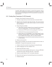
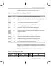
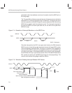
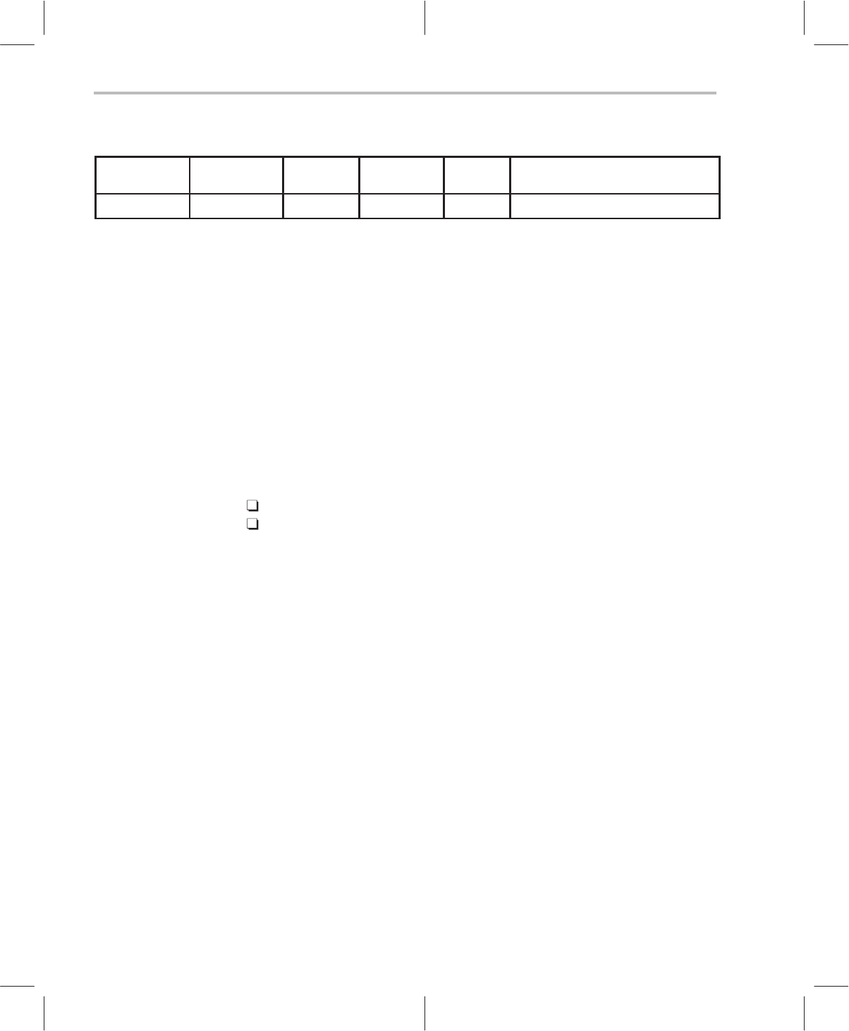
Figure 7–3. MII Frame Format: Write
Start
delimiter
Operation
code
PHY
address
Register
address
Turn-
around
Data
01 01 AAAAA RRRRR 10 DDDD DDDD DDDD DDDD
The clock cycle at the end of a transaction is used to disable the PMI from driv-
ing the MDIO pin after a register read (the quiescent cycle). ThunderLAN sup-
ports an extra feature on the serial management interface whereby the PHY
can interrupt the host. The interrupt is signaled to the host on the MDIO pin one
clock cycle later, during the half of the MDCLK cycle which is high.
MII-managed devices use this serial interface to access the internal register
space as defined in the 802.3 or 802.12. A driver recognizes these devices by
successfully reading the register space. A specific PHY can be found by read-
ing the PHY identifier registers (locations 0x02h and 0x03h) and matching
them to a known code.
For Texas Instruments PHYs and PMIs, these codes are shown below, where
the xx denotes a revision:
0x4000501xx for the internal 10Base-T PHY
0x4000502xx for the TNETE211 100VG-AnyLAN PMI
One performance enhancement that ThunderLAN architecture supports is the
ability to be interrupted by the PHY. This is accomplished through Thunder-
LAN’s enhanced MII. The MII-enhanced interface allows the PHY to interrupt
the host system to indicate that the PHY needs some type of service, rather
than requiring the host to constantly poll the MII registers.
The interrupt mechanism described here is an extension of the 802.3u stan-
dard and does not affect MII compatibility with the existing 802.3u standard.
Servicing an interrupt typically requires the host to read the PHY generic status
register followed by a read of the PHY specific status register. According to the
802.3u, the PHY-specific register is a user-defined register and is normally lo-
cated between the MII registers 0x10 and 0x1f. Texas Instruments has chosen
0x12 as the location for the TLPHY_sts
register.
The MII interrupt bit of this register, MINT, is bit 15, the MSB. This bit indicates
that an interrupt is pending or has been cleared by the current read. The PHY-
specific control register is located at 0x11 and contains two bits of importance,
TINT (test interrupt) and INTEN (interrupt enable). The TINT bit is used to test
the interrupt function; setting this bit forces the PHY to generate an interrupt.
Clearing this bit disables this function. The function of the TINT bit is to test the