


TNETE211 Register Descriptions
B-10
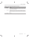
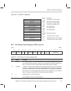
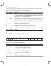
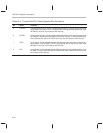
Table B–3. ThunderLAN PHY Control Register Bits
Bit Name Function
15 IGLINK Ignore link: When this bit is set to 0, the 100VG-AnyLAN Demand Priority PHY expects
to receive link pulses from the hub, and sets the LINK bit in the GEN_sts register to
0 if they are not present. When this bit is set to 1, link pulses are ignored and the LINK
bit is always set to 1.
14 MCRS MCRS output value: The MCRS pin of the PMI is deasserted when the transmit/
receive medium is idle. Once the transmit/receive medium is nonidle, the pin is as-
serted.
13 PTLSWEN PMD TLS write control value: The PTLSWEN pin of the PMI is used to control the PMD
TLS write control. It should be set to 0 for all normal operations.
12 PRLSREN PMD RLS read control value: The PRLSREN pin of the PMI is used to control the PMD
RLS read control. It should be set to 0 for all normal operations.
11–6 Reserved Read as 0s
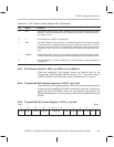
5 TRFAIL Training fail indicator: Writing a 1 to this bit causes the PMI to restart training when the
next window is reached. This bit forces the PMI to interrupt the driver with a retrain
event when retraining occurs.
4 TRIDLE Training idle request: Writing a 1 to this bit causes the PMI to indicate training idle to
the PMD whenever there is no transmit request pending. Writing a 0 to this bit causes
the PMI to send idle up whenever there is no transmit request pending.
3 NPMDW Not physical media dependant wrap: This bit only has meaning when the LOOPBK bit
of the GEN_ctl is a 1. Writing a 1 to this bit causes the PMI to wrap the Tx data to the
Rx data at the far side of the PMI. Writing a 0 to this bit causes the PMI to wrap the
Tx data to the Rx data in the analog device attached to the PMI.
2 NFEW Not far end wrap: This bit only has meaning when the LOOPBK bit of the GEN_ctl is
a 1. Writing a 1 to this bit causes the PMI to wrap the Tx data to the Rx data at the MII
interface. Writing a 0 to this bit causes the PMI to wrap the Tx data to the Rx data based
on the value of the NPMDW bit.
1 INTEN Interrupt enable: Writing a 1 to this bit causes the PMI to generate interrupts to the MII
if any one of the event conditions occur. Writing a 0 to this bit causes the PMI to not
generate an MII interrupt even though an event condition has occurred.
0
TINT Test interrupt: Writing a 1 to this bit causes the PMI to generate an interrupt to the MII.
Writing a 0 to this bit causes the PMI to not generate an MII interrupt. This bit is used
to test the interrupts from the PHY prior to requiring them.