


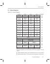
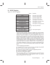

MII PHY Registers
2-18
up resistor, which is recommended to be attached to this line. The MII devices
should see 1s.
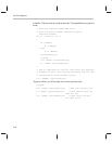
An alternate way to give the PHYs a series of 1s, is to:
set(MDATA)
set(MTXEN)
clr(MCLK);
//delay here
DioRdByte(base_addr,Net_Sio);
set(MCLK);
Where MCLK is a constant for the third LSB (in the internal NetSio register)
and is defined as:
//delay
DioRdByte(base_addr,Net_Sio);
set(NMRST);
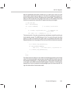
This is the command to set a bit to 0 in the internal NetSio register. In this case,
the MCLK bit in NetSio
is set. Set could be defined this way:
#define set(x)
DioWrByte(base_addr,Net_Sio,(BYTE)(DioRdByte
(base_addr,Net_Sio) |x))
The routine to synchronize the PHYs is part of the startup code. The controller
at this point is held in reset due to the drivers writing a 1 to the Ad_Rst bit, bit
15 in the HOST_CMD register, or a reset being received on power-up through
the PCI system. Setting the NMRST bit to 0 places the MII bus in a reset state.
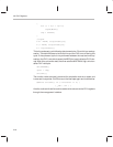
for (i = 0;i < 32;i++)
togLH(MCLK);
The command togLH is a combination of the clr and set commands on the
passed parameter and is defined this way:
#define togLH(x) {clr(x); \
set(x);}
}
togLH is repeated 32 times to give PHYs the 32, 1 data bits that they need to
get synchronized. Note that the clock line is left in the high state at the end of
the loop.