


PCI Configuration Registers
A-4
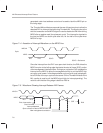
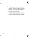
The first bit written to or read from the EEPROM is the most significant bit of
the byte, such as data(7). Therefore, writing the address C0h is accomplished
by writing a 1 and six 0s.
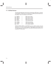
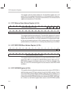
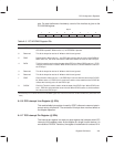
ThunderLAN expects data to be stored in the EEPROM in a specific format.
Nine bytes in the EEPROM are reserved for use by the adapter, starting with
C0h, as shown below. The contents of the remaining 247 bytes are undefined.
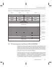
The EEPROM can also be read from or written to by driver software through
the NetSio register. The shaded registers in Figure A–1 can be autoloaded
from an external serial EEPROM.
Figure A–2. Configuration EEPROM Data Format
Address
C8h
C7h
C6h
C5h
C4h
C3h
C2h
C1h
C0h
Checksum
Max_Lat
Min_Gnt
Subclass
Revision
Device ID MSByte
Device ID LSByte
Vendor ID MSByte
Vendor ID LSByte
Any accesses to the adapter’s configuration space during autoload are re-
jected with a target retry. The checksum byte is an 8-bit cumulative XOR of
the eight shaded bytes, starting with an initial value of AAh. The adapter uses
this checksum to validate the EEPROM data. If the checksum fails, the config-
uration registers are set to their default (hardwired) values instead.
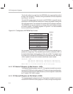
Checksum = AAh
XOR Data(0) XOR Data(1) XOR Data(2) XOR Data(3)
XOR Data(4) XOR Data(5) XOR Data(6) XOR Data(7);
Where XOR is a bitwise exclusive OR of the bytes.
A.1.2 PCI Vendor ID Register (@ 00h) Default = 104Ch
This register holds the adapter vendor ID. This register is loaded from an exter-
nal serial EEPROM on the falling edge of PCI reset, during autoconfiguration.
Should autoconfiguration fail (bad checksum), then this register is loaded with
the TI vendor ID of 104Ch instead.
A.1.3 PCI Device ID Register (@ 02h) Default = 0500h
This register holds the adapter device ID. The register is loaded from an exter-
nal serial EEPROM on the falling edge of PCI reset, during autoconfiguration.