


MII PHY Registers
2-23
ThunderLAN Registers
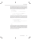
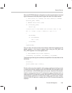
After the addresses have been clocked out on a read cycle, there is a cycle
where neither side drives the data pin. If the PHY is synced and ready to re-
spond, it should drive a 0 next, followed by the 16 bits of data. The data is avail-
able up to 300 ns after the rising edge of the clock, so the software loop uses
that time to execute the instruction to make the clock go low again.
// Get PHY Ack
ack = inp(diodata);
if (!(ack & MDATA)) // if ack=0, record bits
{
b |= MCLK; outp(diodata,b); // complete ack
cycle clock
for (tmp = 0,i = 0x8000;i;i >>= 1)
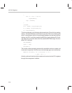
The loop is set for 16 cycles, using the loop variable as a mask for pointing to
the bit position stored. The MSB comes in first. For each shift cycle, the clock
goes up to start the access and goes down to guarantee that some time
elapses between the rising edge of the clock and the time the data is sampled.
{
b &= ~MCLK; outp(diodata,b);
if (inp(diodata)&MDATA)
tmp |= i; //if data bit=1, or position in
b |= MCLK; outp(diodata,b);
}
}
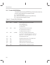
else
If the PHY does not respond, one needs to complete the access cycle to keep
other PHYs from being left in mid-access. Leave the MDIO pin set for input but
set the data variable to all 1s. This routine gives 17 clock cycles, using the mac-
ro for togHL on the MCLK bit of the NetSio register. There are 17 clock cycles,
because the first one finishes the acknowledge cycle (the clock was left in a
logic low state when the data was read).