


Adapter Internal Registers
A-35
Register Definitions
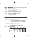
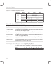
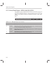
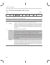
Table A–16. Adapter Commit Register Bits
Bit Name Function
31–28 Tx commit
level
Transmit commit level: This nibble code indicates the commit size in use by the adapter
transmitter. The code indicates the number of bytes that must be in a channel’s FIFO
before network transmission is started. At reset, the commit level is set to 0, giving mini-
mum latency. It is incremented every time a frame is aborted due to a FIFO underrun.
The adapter, therefore, automatically adapts itself to the latency available on the host
bus. Every increment in level corresponds to a doubling of latency size.
The commit levels are:
0: 64 bytes
1: 128 bytes
2: 256 bytes
3: 512 bytes
4: 1024 bytes
5–7: whole frame
When the transmit commit level is 3 or greater (512 bytes or more), transmission begins
if a FIFO deadlock condition occurs. If the transmitter is waiting for required data in the
FIFO and the next PCI data transfer is waiting for room to be freed up in the FIFO before
it starts, a deadlock situation exists and transmission never starts. The deadlock is bro-
ken by detecting this condition and allowing network transmission to proceed before the
full commit level is reached. This situation only occurs where large commit levels are
combined with large fragment, burst, and frame sizes.
27–24 PHY options When ThunderLAN is configured for a bit-rate CSMA/CD MII (BITrate option bit in the
NetConfig register), the contents of these bits are presented on the MTXD[3::1] and
MTXER pins to allow selection of PHY options. Pin mapping is as follows:
Bit 27 – MTXD3 (full duplex disable)
Bit 26 – MTXD2 (loopback enable)
Bit 25 – MTXD1 (10Base-T (0)/AUI-ThinNet (1) select)
Bit 24 – MTXER (reserved (0))
All bits in this register are set to 0 on an Ad_Rst or when PRST# is asserted.
The MSnibble of this register can be written to only when the adapter is in reset
(NRESET bit is set to 0).
A.3.12 LED Register–LEDreg @ 0x44 (DIO) (Byte 0)
This byte register contains the value that is driven on the EAD pins whenever
BIOS ROM accesses are not taking place (when EXLE, EALE and EOE# are
all inactive). Light emitting diodes (LEDs) connected to the EAD pins (directly
or buffered) can be controlled by software through this register. All bits in this
register are set to 0 on an Ad_Rst or when PRST# is asserted. The values that
are output on the EAD pins are the inverse of those which are written to LEDreg.