


Register Addresses
2-2
2.1 Register Addresses
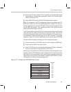
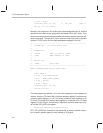
The following figure shows the various register spaces provided by Thunder-
LAN. It also shows how a driver uses ThunderLAN’s registers to interface to
external devices such as PHYs, BIOS ROMs, and EEPROMs.
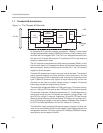
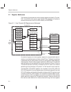
Figure 2–1. How ThunderLAN Registers are Addressed
Host registers
HOST CMD
CH PARM
HOST INT
DIO ADR
DIO DATA
PCI
PCI registers
Memory
base address
BIOS ROM
base address
PCI NVRAM
I/O base
address
NetCmd
NetSts
NetSio
AREG0–3
HASH
Statistics
registers
LEDreg
Internal/DIO registers
MDIO/MDCLK
MII/PHY registers
Generic
Autonegotiation
Reserved
PHY specific
Serial EEPROM
BIOS ROM
LED
EDIO/EDCLK
LED IF
ThunderLAN
SRAM
One block of registers, the host registers, appear at a programmable place in
memory or port address space, directly on the PCI bus. The beginning address
is determined by the value written into the PCI configuration space base ad-
dress registers. Once the base register’s address is determined, ThunderLAN
reads and writes to these registers like ordinary memory or I/O ports. Since the
ThunderLAN devices are directly connected to the PCI, there is no external
decode logic that generates a chip select—all the decode is done internally.
ThunderLAN’s internal/DIO registers are accessed via the DIO_ADR and
DIO_DATA registers in the host register group. An address is placed in the host
DIO_ADR register, and the data to be read or written to the DIO register is read
or written to the DIO_DATA register. The internal/DIO register space is refer-
enced indirectly via the host registers to minimize the amount of host address
space required to support the ThunderLAN controller. External devices and
their data are also reached via indirect reference through the host registers