


PCI Configuration Registers
A-3
Register Definitions
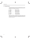
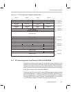
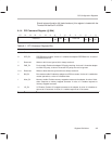
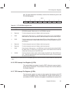
Figure A–1. PCI Configuration Register Address Map
read only
read/write
read/write
read/write
read/write
read/write
read/write
read only
read/write
read only
Byte 0Byte 1Byte 2Byte 3
031
FFh
44h
40h
3Ch
38h
34h
30h
2Ch
18h
14h
10h
0Ch
08h
04h
00h
Reset control
Interrupt lineInterrupt Pin(01h)Min_GntMax_Lat
Reserved (00h)
Reserved (00h)
Reserved (00h)
BIOS ROM base address
Memory base address
I/O base address
size
Cache line
timer
LatencyReserved
(00h)
(00h)
Reserved
Revision
(00h)
Program interface
Subclass
(02h)
Base Class
Vendor IDDevice ID
Status Command
Cardbus CIS Pointer
Reserved (00h)
Reserved (00h)
Reserved (00h)
Reserved (00h)
PCI NVRAM
Reserved (00h)
Reserved (00h)
IntDis
28h
read only
48h
B4h
read only
Reserved (00h)
A.1.1 PCI Autoconfiguration from External 24C02 Serial EEPROM
ThunderLAN allows some of the PCI configuration space registers to be
loaded from an external serial EEPROM. These registers contain fixed vendor
and device information. Autoconfiguration allows builders of ThunderLAN sys-
tems to customize the contents of these registers to identify their own systems,
rather than using the Texas Instruments defaults.
The state of the EDIO pin during PCI reset (PRST#), enables (high) or disables
(low) autoconfiguration. In order to use a 24C02 EEPROM, the EDIO line re-
quires an external pullup. ThunderLAN enables autoconfiguration if it detects
this pullup (EDIO high) during PCI reset. If autoconfiguration is not required
or no EEPROM is present, the EDIO pin must be tied to ground.