


PCI Configuration Registers
A-7
Register Definitions
A.1.6 PCI Base Class Register (@ 0Bh)
This register is hardwired with the network controller code of 0x02h.
A.1.7 PCI Subclass Register (@ 0Ah)
This register holds the adapter PCI subclass. This register is loaded from an
external serial EEPROM on the falling edge of PCI reset, during autoconfi-
guration. Should autoconfiguration fail (bad checksum), then this register is
loaded with the other network controller code of 0x80h (there are no codes al-
located to multiprotocol adapters).
A.1.8 PCI Program Interface Register (@ 09h)
This register is hardwired to 0 (no defined interface).
A.1.9 PCI Revision Register (@ 08h)
This register holds the adapter’s revision. This register is loaded from an exter-
nal serial EEPROM on the falling edge of PCI reset, during autoconfiguration.
Should autoconfiguration fail (bad checksum), this register is loaded with
0x20h to indicate pattern generation 2.0 (PG 2.0) ThunderLAN.
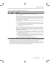
A.1.10 PCI Cache Line Size Register (@ 0Ch)
This register informs the adapter of the memory system cache line size. This
is used to determine the type of memory command used by ThunderLAN in
PCI bus master reads.
Memory read line is used for data reads of less than four cache lines.
Memory read multiple is used for data reads of four or more cache lines.
A cache line size of 0 (default register state after reset) is interpreted as a
cache line size of 16 bytes. Cache line sizes must be powers of 2 (0, 1, 2, 4,
8, 6, 32, 64, 128); values that are not powers of 2 are rounded down to the near-
est power of 2. This register is loaded with 0 at reset.
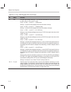
A.1.11 PCI Latency Timer Register (@ 0Dh)
This register specifies in units of PCI bus clock cycles, the value of the adapter
latency timer. This register is loaded with 0 at reset.
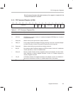
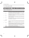
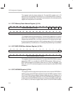
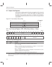
A.1.12 PCI I/O Base Address Register (@ 10h)
16171819202122232425262728293031
I/O base address 16 MSBs
1000
I/O base address 12 LSBs
0123456789101112131415