


Adapter Host Registers
A-19
Register Definitions
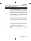
and Nes bits. This allows the value read from the interrupt register to be written
to the HOST_CMD register to directly select the appropriate channel. If no in-
terrupts are active, the interrupt pacing timer is running, or the PCI interrupt
has been disabled (by writing a nonzero value to this register), the HOST_INT
register is read as all 0s. If this value (0) is written to HOST_CMD (with the Ack
bit set) no interrupts are acknowledged but the interrupt pacing timer is re-
started.
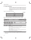
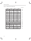
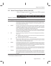
A.2.4 DIO Address Register–DIO_ADR @ Base_Address + 8 (Host)
ADR
INC
0123456789101112131415
ADR_SEL
RAM
ADR
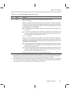
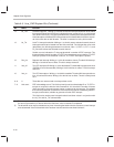
Table A–7. DIO
_
ADR Register Bits
Bit Name Function
15 ADR_INC Address increment: When this bit is set to a 1, the DIO address in ADR_SEL autoincre-
ments by 4 on each DIO_DATA access. When this bit is set to 0, the DIO address is not
affected by accesses to DIO_DATA.
14 RAM_ADR RAM address select: When this bit is set to 1, DIO accesses are to the muxed SRAM.
If this bit is set to 0, DIO accesses are to internal ThunderLAN registers. The internal
muxed SRAM can only be accessed while the adapter is in reset (NRESET bit in the
NetCmd register is set to a 0). Accesses to the SRAM while the adapter is not in reset
are undefined; they are ignored and return unknown data.
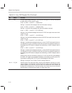
13–0 ADR_SEL
†
This field contains the DIO address, the SRAM or the internal register address to be used
on subsequent accesses to the DIO_DATA register. If the ADR_INC bit is set, this field
autoincrements by 4 on accesses to the DIO_DATA register.
For register accesses, the seven MSBs [13::7] of ADR_SEL are ignored. The seven
LSBs [6::0] indicate the byte address of the register, but the two LSBs are not used
since byte control is through the PCI bus byte enables.
For RAM, accesses to the three MSBs [13::11] of ADR_SEL are ignored. The 11
LSBs [10::0] indicate the RAM row address [10::2] and RAM word address [1::0].
†
This is a byte address.
RAM Addressing
The RAM is composed of 431, 68-bit words. Bits [10::2] of ADR_SEL indicate
the ROW address. Bits [1::0] are used to indicate which part of the 68-bit word
is to be accessed.