


Initializing
3-7
Initializing and Resetting
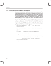
3.1.5 Recovering the Silicon Revision Value
At this point, the sample program needs to know what the default silicon revi-
sion for the controller is. There is a revision byte in the configuration space that
can be read with a PciRdxxxx command. This configuration byte is loaded with
EEPROM data to signal the board-level revision code. If the EEPROM data is
bad or nonexistent, a value for this byte is hardwired in an internal register at
location 0x0c. This byte indicates the silicon revision. However, once the
memory and I/O access modes are turned on, one can read this register direct-
ly and get the silicon revision, regardless of whether this default value was
needed in the PCI initialization. With this arrangement, the driver can find the
silicon revision and the board revision.
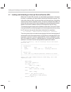
nic.Rev = DioRdByte(nic.IoBase,NET_DEFREV);
...
#define NET_DEFREV 0x0C //default revision reg
DioRdByte calls a routine that loads the host DIO_ADR register with
NET_DEFREV and does a byte-enabled read of the host DIO_DATA register,
returning the value to the member rev value of DIO_DATA for structure nic.
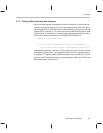
3.1.6 Setting the PCI Bus Latency Timer
An additional step that must be performed in the PCI configuration section of
the code is to set the latency timer to the maximum value of 0xff. It had been
loaded with 0 at reset. The instruction is:
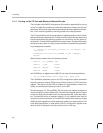
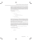
PciWrByte(nic.DevId,PCI_LATENCYTIMER,0xFF);
...
#define PCI_LATENCYTIMER 0x0D
Where PciWrByte is a register-level interrupt 86 (int86) O/S call for reading PCI
configuration space, nic.devId is the NIC’s PCI system identifier discovered
above, and PCI_LATENCYTIMER is a constant representing the offset into
the PCI configuration space of that byte.